

X-Ray Scattering
X-ray scattering illuminates a sample with photons whose wavelength is comparable to an interatomic spacing, then records where the scattered photons go, how much energy they lose, and sometimes how their polarization changes. Far from an absorption edge, the leading elastic signal maps electron-density-weighted crystal structure. Near an edge, virtual core excitation makes the amplitude element, valence, orbital, and polarization selective. Coherent beams add speckle and phase-retrieval information, while energy analysis exposes phonons and electronic collective excitations.
Those capabilities do not make a detector image a direct picture of atoms or charge order. The measured counts combine the sample amplitude with flux, polarization, geometry, absorption, fluorescence, detector response, reciprocal-space acceptance, and resolution. In coherent diffraction, the detector ordinarily loses the scattered phase. Near resonance, the same edge that enhances contrast also changes attenuation and can make the scattering amplitude tensorial.
For example, an extra diffraction peak locates an additional spatial periodicity. Its intensity, polarization dependence, and energy dependence help distinguish atomic displacements from changes in electronic charge or orbital states. The following sections develop those distinctions from the scattering amplitude.
Required background. Reciprocal Lattice supplies diffraction geometry and reciprocal-vector indexing. Structure Factors supplies the relation between spatial or dynamical correlations and momentum-resolved intensity. How Quantum Matter Is Measured supplies calibration, resolution and the distinction between measured intensity and an inferred material structure.
X-ray scattering from charge and structure
Section titled “X-ray scattering from charge and structure”X-rays primarily couple to electrons. Spatial interference tells us about structure; resolving the outgoing photon energy adds information about dynamics. We begin with weak, single scattering, where the outgoing wave is the sum of contributions from the illuminated sample. Strong multiple scattering in a nearly perfect crystal requires dynamical diffraction theory.
The historical experiments are described in X-Ray Experiments. Here the emphasis is how to interpret modern material measurements.
Wavelength, momentum, and energy transfer
Section titled “Wavelength, momentum, and energy transfer”For a photon in vacuum,
A convenient conversion is
Thus a hard X-ray has , comparable with crystal spacings. Soft X-rays near transition-metal edges have longer wavelengths and lower penetration depths, but offer direct dipole access to valence-sensitive intermediate states.
Adopt the target-transfer convention
Here is a wavevector transfer; the physical momentum delivered to the sample is . Positive means that the sample gains energy. If is the angle between incident and outgoing beams, elastic scattering has
The accessible reciprocal-space region is therefore set by photon energy, scattering angle, sample orientation, and mechanical shadowing. A nominally accessible reflection can still be blocked by a cryostat, pressure cell, beamstop, detector gap, or polarization geometry.
Thomson amplitude and polarization
Section titled “Thomson amplitude and polarization”For a free electron initially at rest, neglecting recoil at photon energies , the Thomson cross section for specified incoming and outgoing polarizations is
where
is the classical electron radius. The polarization factor is part of the forward model, not a cosmetic correction. Synchrotron radiation is usually strongly polarized, and an analyzer can separate outgoing polarization channels. Even without an analyzer, the detector sums only over the outgoing states admitted by its geometry.
For an isolated atom with electron number density , the nonresonant amplitude in electron units is
The forward amplitude counts the electrons: for a neutral atom and for an ion of charge . Because the electron cloud has finite extent, generally decreases with . X-ray diffraction therefore weights heavy atoms strongly at small momentum transfer and can have weak contrast for light atoms beside heavy ones. This contrasts with neutron scattering lengths, which vary irregularly across elements and isotopes.
The Fourier integral permits an anisotropic electron density; only a spherical density reduces it to a function of alone. Treating a crystal as a sum of such isolated atoms is an additional approximation. Bonding charge, magnetization, and resonant transitions can require more detailed amplitudes. The IUCr structure-factor introduction explains the connection between atomic positions and interference.
Crystal Structure from Elastic Diffraction
Section titled “Crystal Structure from Elastic Diffraction”Lattice sum and unit-cell amplitude
Section titled “Lattice sum and unit-cell amplitude”Let label unit cells and the position of atom inside a cell. In the kinematic approximation, the elastic amplitude separates into
with
Here is occupancy, is the atomic amplitude (with any tensor contracted with the selected incoming and outgoing polarizations), and is the amplitude Debye–Waller factor. For a Gaussian displacement tensor ,
The lattice sum concentrates an ideal infinite-crystal signal at reciprocal vectors . The unit-cell amplitude decides the relative intensity and systematic absences. A reciprocal-lattice point is therefore a possible Bragg position, not a guarantee of nonzero intensity.
This formula also shows why structure determination is an inverse problem. Positions, occupancies, displacement parameters, atomic form factors, scale, extinction, preferred orientation, and domain fractions can be correlated. A low residual does not prove that every parameter is identifiable.
Bragg positions and integrated intensities
Section titled “Bragg positions and integrated intensities”At an elastic Bragg condition,
with , so
The alternative notation holds the plane family fixed and labels its harmonics by . That harmonic has ; the order is already included when the reflection is indexed by its full Miller indices.
Peak positions constrain the lattice metric and orientation. Integrated intensities constrain the motif. Peak shapes constrain finite size, strain distributions, defects, mosaicity, correlations, and instrumental resolution. These statements are cleaner than saying that a diffraction pattern simply “shows the structure.”
A schematic integrated-intensity model is
where is incident flux, is exposure, is the multiplicity when symmetry-equivalent powder reflections are combined, and are geometry and polarization factors, is absorption, represents extinction or other sample-dependent corrections, and is background. The exact factors depend on powder, single-crystal, grazing-incidence, reflectivity, and area-detector geometry.
Correction order matters. A pixel mask and dark subtraction precede geometric integration; monitor normalization must use a linear incident-flux record; dead-time correction must precede comparisons across count rate. Applying a software “Lorentz-polarization correction” without stating the scan geometry is not reproducible.
Powder, single-crystal, and thin-film measurements
Section titled “Powder, single-crystal, and thin-film measurements”Powder diffraction collapses three-dimensional reciprocal-space shells onto or . It is efficient for phase identification and lattice parameters but creates peak overlap, preferred-orientation sensitivity, and limited access to diffuse anisotropy. Rietveld refinement compares the full pattern with a structural and instrumental model; it does not turn each visible peak into an independently measured structure factor.
Single-crystal diffraction retains directional information. Rocking, rotation, and detector scans sample a three-dimensional reciprocal-space volume. Orientation matrices, detector distance and tilt, wavelength, goniometer offsets, and sample displacement must be calibrated together. Symmetry-equivalent reflections test corrections and crystal quality.
Thin films and interfaces introduce truncation rods, finite-thickness fringes, substrate peaks, refraction near grazing incidence, footprint variation, and multiple orientation domains. A broad feature may reflect thickness or mosaic spread rather than a short intrinsic correlation length. Reciprocal-space maps should preserve both in-plane and out-of-plane coordinates before any one-dimensional cut is interpreted.
The phase problem and refinement
Section titled “The phase problem and refinement”An ordinary detector records intensity,
not the complex phase of . For nonresonant electron-density structure factors, an inverse Fourier series would require both:
A complex resonant tensor amplitude is not simply the Fourier coefficient of the ground-state electron density, so this inversion cannot be applied to it without a scattering model. Crystallographic phase information is supplied indirectly by symmetry, chemical constraints, direct or dual-space methods, anomalous contrast, molecular replacement in suitable settings, or refinement from an initial model. A Fourier map reconstructed from model phases is not independent confirmation of that model.
A defensible refinement reports the structural model, scattering-factor tables, constraints and restraints, excluded regions, absorption and extinction treatment, goodness-of-fit measures, parameter covariance or uncertainty, residual density, and tests against plausible alternative space groups or domain models.
Peak Widths, Diffuse Scattering, and Correlations
Section titled “Peak Widths, Diffuse Scattering, and Correlations”Finite correlation length replaces an ideal reciprocal-space delta peak by a profile. For an exponentially decaying one-dimensional correlation,
the Fourier transform contains two Lorentzians, centered at :
When , the peaks are well separated. Near one then obtains the familiar isolated line
After separating the opposite satellite and any background, its intrinsic half width at half maximum is . This conversion is model and convention dependent. A Lorentzian-squared profile, finite domain, algebraic correlation, anisotropic disorder, or distribution of lattice constants gives a different relation. Instrument resolution must be convolved with the intrinsic profile before is reported.
Diffuse scattering between Bragg peaks can reveal short-range order, correlated displacements, stacking faults, chemical disorder, thermal motion, and critical fluctuations. It is often weak compared with air, windows, fluorescence, Compton scattering, substrate, and detector backgrounds. Subtracting a high-temperature pattern can isolate a changing component, but it also removes everything that is temperature independent and mixes thermal-expansion shifts into derivative-like residuals.
Integrated intensity, peak height, and width carry different information. If a peak narrows while conserving integrated weight, its maximum grows without a corresponding growth of total correlation strength. Report the fitted profile and integrated area, not only the brightest pixel.
Resonant X-Ray Scattering
Section titled “Resonant X-Ray Scattering”Complex and tensor form factors
Section titled “Complex and tensor form factors”Near a core-level absorption edge, the scalar anomalous form is often written
is tied to absorption and to it through a dispersion relation. Tabulated free-atom values are useful far from sharp chemical structure, but a resonant experiment deliberately works where oxidation state, ligand field, hybridization, symmetry, and polarization can invalidate a purely scalar table.
A more faithful electric-dipole amplitude is a tensor:
The tensor contains amplitudes for exciting and de-exciting core states, with their polarization-dependent matrix elements and finite lifetimes. The Kramers–Heisenberg expression below displays those intermediate states explicitly. Higher multipoles can matter where electric-dipole transitions are weak or forbidden. When combining a resonant calculation with a structural amplitude, use consistent phase and scattering-factor conventions; relative phases determine their interference.
The tensor character is an opportunity and a warning. Incident energy, incident and outgoing polarization, azimuthal angle, scattering plane, and crystal orientation can distinguish scalar charge, anisotropic orbital, and magnetic channels. The same dependencies also mean that a single energy scan at one geometry rarely determines a unique microscopic tensor.
Resonance does not remove absorption
Section titled “Resonance does not remove absorption”The incident and outgoing waves both attenuate inside the sample. Consider a flat uniform slab of normal thickness , with both beams crossing the same surface. Let be their positive angles to that surface and their intensity attenuation coefficients. A scattering event at normal depth receives the intensity weight , where
For uniform sources whose contributions from different depths add incoherently, the effective contributing depth is
This has units of length. The attenuation relative to the same unattenuated slab is , which tends to one for and to for . Fluorescence is a useful example; its yield also contains the energy-dependent excitation probability and branching fraction, not just this depth factor. Booth and Bridges derive that geometry explicitly.
For a coherently illuminated crystalline slab, add amplitudes first. In a scalar kinematic model, with constant local scattering amplitude and normal mismatch from the Bragg condition,
The factor appears because field amplitudes decay as the square root of intensity. At exact Bragg alignment the attenuation relative to an unabsorbed peak is
This is a peak intensity, not a universal correction for integrated diffraction. Integrating the whole idealized profile over gives by Parseval’s identity. The measured scan range and geometry therefore matter. Refraction, dynamical diffraction, layering, finite footprint, and standing waves can invalidate this simple slab calculation.
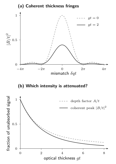
Top: versus the dimensionless mismatch for an unabsorbed slab and for . Interference creates the thickness fringes; absorption changes their shape. Bottom: the depth factor and the coherent peak factor both approach one in a thin slab, but differ at larger optical thickness. Each curve is normalized to its own unabsorbed signal. The curves follow the equations above, without instrumental broadening or multiple scattering.
Near an edge, the scattering amplitude and attenuation both change. For elastic photons, and the homogeneous material has the same absorption coefficient at entry and exit. A fluorescence photon instead has a different, approximately fixed energy while is scanned. Comparing angles, outgoing-energy channels, and off-resonance scans helps separate these effects; dividing a diffraction trace by an arbitrary absorption trace does not.
Charge Order
Section titled “Charge Order”A charge or orbital modulation at wavevector produces satellite intensity near
for a real single-harmonic modulation, together with symmetry-related positions. The paired positions do not require equal measured intensities: polarization, absorption, and complex resonant scattering factors can distinguish them. Higher harmonics can produce additional satellites. Nonresonant intensity may arise primarily from atomic displacements induced by the order. Near an absorption edge, a spatial modulation of the resonant tensor adds element- and orbital-selective contrast:
The two amplitudes interfere. Intensity alone does not generally separate lattice displacement from valence or orbital modulation because
contains a cross term and loses the overall phase.
To identify charge order, compare the satellite positions and widths with their temperature dependence and with the predicted energy, polarization, and azimuthal response. Off-resonance diffraction tests accompanying lattice displacements. Symmetry-related scans and a second probe help distinguish a genuine modulation from multiple diffraction, a substrate reflection, or beam damage. The 2012 measurements of Ghiringhelli and collaborators and the review by Comin and Damascelli illustrate how these tests constrain cuprate charge correlations.
Resonant enhancement identifies sensitivity to states associated with the chosen edge. It does not directly count “holes per site” without a calibrated microscopic model. Nor does a finite-width quasielastic peak prove truly static order: the statement is limited by energy resolution and acquisition time.
The phase physics, nesting question, reconstructed bands, collective modes, and competition with superconductivity remain at Charge and Spin Density Waves.
Coherent Diffraction
Section titled “Coherent Diffraction”Speckles carry spatial information
Section titled “Speckles carry spatial information”If the illumination is coherent across the relevant sample region, amplitudes from different points interfere with stable relative phase. A finite, nonuniform object produces a speckle pattern rather than a smooth ensemble-averaged intensity. In the far field and single-scattering approximation, for uniform coherent illumination,
This is a three-dimensional Fourier transform sampled on the accessible scattering surface. A two-dimensional projection approximation additionally neglects longitudinal phase variation and replaces by its density integrated along the incident beam. The detector still records only the modulus squared. Coherent diffraction imaging uses oversampling plus constraints such as finite support, positivity where justified, measured amplitudes, overlap, or known reference structure to recover a compatible complex object iteratively.
Oversampling supplies additional constraints for the common isolated-object reconstruction problem, but it does not guarantee a unique or correct reconstruction; the requirements change when known references or overlapping probe positions supply information. Missing central pixels behind a beamstop, saturation, partial coherence, background, finite detector range, position jitter, probe uncertainty, and stagnation of the phase-retrieval algorithm can create families of solutions. Reconstruct from multiple random starts, show convergence metrics, propagate data uncertainty, and test the result by forward diffraction.
Bragg coherent diffraction and ptychography
Section titled “Bragg coherent diffraction and ptychography”Near a reciprocal vector , a strained crystalline object can be represented schematically as
The reconstructed amplitude reflects shape, composition, and coherent crystalline fraction. Its phase constrains the displacement projection
The sign here follows the positive Fourier phase used above. One reflection gives one displacement projection. An arbitrary constant phase leaves all diffraction intensities unchanged, so an absolute rigid translation cannot be recovered. Changing the reciprocal-space origin adds a linear phase ramp and changes the reference for mean strain. After choosing those references, spatial phase gradients constrain displacement gradients. At least three linearly independent reflections with common spatial registration are needed for the three displacement components; phase wrapping and crystal defects must also be treated. Yang and collaborators discuss practical strain reconstruction.
Ptychography scans an overlapping coherent probe across an extended sample and jointly infers probe and object. Bragg ptychography combines that redundancy with lattice sensitivity. These methods are computational microscopes, but their spatial resolution is supported by reproducible transfer and phase-retrieval tests, not merely by reconstruction pixel size.
Time-dependent speckle correlations form X-ray photon correlation spectroscopy. A common normalized observable is
For stationary, zero-mean, jointly circular complex Gaussian scattered fields, with no coherent reference mixed into the signal, the Siegert relation gives
where is the normalized field correlation and describes measured speckle contrast. Relating to a material correlation function requires the scattering model. A coherent static reference introduces heterodyne terms; non-Gaussian fields need not satisfy this relation. Photon self-counting at zero delay and finite exposure need separate treatment. For aging samples the correlations may depend on both observation times, as explained by Bikondoa. Beam-induced motion and detector afterglow can mimic dynamics.
Inelastic X-Ray Scattering
Section titled “Inelastic X-Ray Scattering”Resolving the outgoing photon energy distinguishes fluctuations by how much energy they exchange with the sample. A phonon produces a small loss or gain; electronic excitations can appear at much larger transfers.
Nonresonant inelastic scattering
Section titled “Nonresonant inelastic scattering”Away from an absorption edge, the nonresonant density coupling gives
where and is the total illuminated-sample electron-density spectrum per unit energy, not per electron. With , our positive target-transfer convention uses
Here is the initial-state probability. If a spectrum is instead defined with , then . A per-particle definition also requires restoring its particle-number factor. Baron’s review develops the cross section with an energy-normalized spectrum; compare Fourier and momentum signs before transferring a formula between references.
For small energy transfers in a crystal, an atom’s electrons largely follow its nucleus, leading to atomic form factors and phonon displacement correlations. High-resolution IXS can measure these modes in small samples and pressure cells. Higher-energy density scattering can reveal plasmons and particle–hole continua. Multiphonon contributions, Compton scattering, and instrumental resolution still shape the measured spectrum. See Structure Factors for correlation-function normalization and sum rules.
Resonant inelastic X-ray scattering
Section titled “Resonant inelastic X-ray scattering”Resonant inelastic X-ray scattering, or RIXS, tunes near an absorption edge and resolves . For an initial pure material state in the resonant electric-dipole approximation, its Kramers–Heisenberg intensity is schematically
Here is the outgoing photon energy, while , , and are material-state energies. The ket labels the final material state. At finite temperature, average these intensities over initial states with their probabilities. The widths are in energy units. The review by Ament and collaborators derives this expression and the assumptions behind its simpler effective operators.
The intermediate core hole, dipole selection rules, polarization, edge, and interference among intermediate states shape the spectrum. A RIXS intensity is therefore not generally one universal . In controlled limits, effective operators connect particular channels to spin, orbital, charge, or lattice correlation functions. Outside those limits, multiplet, band, cluster, or many-body calculations are part of the inference.
Typical energy-loss features include:
| Feature | Typical interpretation | Essential caution |
|---|---|---|
| elastic or quasielastic line | static or slow order, diffuse scattering | unresolved phonons, drift, and instrumental tails |
| phonon progression | lattice excitation and electron–phonon coupling | self-absorption and unresolved modes alter weights |
| magnon or multimagnon feature | spin excitation in a resonantly allowed channel | polarization and model-dependent effective operator |
| crystal-field or – excitation | local orbital or multiplet transition | hybridization and site symmetry matter |
| charge-transfer excitation | ligand–metal or interband process | broad continua need a material calculation |
| plasmon or particle-hole continuum | collective or incoherent charge dynamics | background and channel mixing |
A resonant scan with no outgoing-energy analysis integrates all energies admitted by the detector, including unresolved inelastic scattering and fluorescence. Calling the resulting signal elastic requires additional justification. RIXS separates energy loss, at a substantial cost in throughput.
From detector pixels to scattering intensity
Section titled “From detector pixels to scattering intensity”A laboratory diffractometer can measure lattice parameters, phases, and many structural changes with a characteristic tube line. Synchrotron sources add tunable energy, controlled polarization, focused beams, and coherent flux. The relevant quantities are the measured energy bandwidth, beam size and divergence, polarization purity, and flux at the sample.
An area-detector pixel becomes a scattered ray only after calibrating beam center, sample-to-detector distance, detector rotations, and pixel size. A powder or crystal standard constrains the geometry; the sample orientation maps laboratory wavevectors to reciprocal coordinates. Inspect calibration residuals across the detector: matching one peak does not ensure that a whole reciprocal-space map is accurate.
Independent ideal photon counts have Poisson variance equal to their mean. Dark subtraction, normalization by a fluctuating monitor, interpolation, and pixel merging change the uncertainty and can create correlations. Detector dead time, saturation, charge sharing, and drift require additional checks. Repeated short exposures help distinguish these effects from photon counting noise.
Forward Model and Corrections
Section titled “Forward Model and Corrections”For incident flux density and exposure time , a useful expected-count model is
The sample cross section includes the illuminated material and its attenuation; is the dimensionless probability that an outgoing photon reaches bin , including resolution and acceptance, is efficiency, and is expected background. This expression has the units of counts. Average it over the incident spectrum or time-varying beam when necessary. Elastic scattering contributes a delta function in .
A map in is a change of coordinates with an associated measure and Jacobian. A fixed incident beam and energy do not sample an arbitrary four-dimensional volume; rotations and energy scans provide additional coverage.
Resolution is multidimensional
Section titled “Resolution is multidimensional”Angular divergence, beam bandwidth, footprint, sample mosaic, scan step, detector point-spread, analyzer acceptance, and energy bandwidth produce a coupled resolution volume. A one-dimensional Gaussian width subtracted in quadrature is justified only when both intrinsic and resolution profiles are Gaussian in the fitted coordinate and cross-coordinate coupling is negligible.
For weak or resolution-limited peaks, fit the intrinsic model after convolution with a measured or simulated resolution function. Report upper or lower bounds when the data do not identify both intrinsic width and amplitude.
Background is a physical model
Section titled “Background is a physical model”Air, windows, substrate, sample mount, fluorescence, Compton scattering, and neighboring Bragg tails can all contribute. Multiple diffraction and harmonic contamination may create sharp peaks, while detector gaps or hot pixels create instrumental features.
An off-sample region may not reproduce sample fluorescence or absorption. An off-resonance scan changes both contrast and attenuation. A high-temperature scan may contain real critical or structural scattering. Treat each subtraction as a measured control with its own exposure, normalization, and uncertainty.
Radiation damage and nonequilibrium
Section titled “Radiation damage and nonequilibrium”X-rays can heat, ionize, charge, reduce, oxidize, desorb, create defects, move domain walls, or alter strain. The absence of visible surface damage is not a sufficient test. Repeat short scans at fresh positions, vary dose rate and total dose independently, monitor a stable structural reflection, and record time order. A signal that evolves monotonically with exposure is not an equilibrium temperature trend.
What Each X-Ray Mode Can Establish
Section titled “What Each X-Ray Mode Can Establish”| Mode | Primary data product | Strong inference | Persistent ambiguity |
|---|---|---|---|
| powder diffraction | intensity versus or | phases, lattice metrics, average structure | overlap, texture, minority phases |
| single-crystal diffraction | three-dimensional Bragg intensities | symmetry, motif, domains, displacement parameters | phase problem, extinction, model covariance |
| diffuse scattering | intensity between Bragg positions | short-range correlations and disorder models | nonunique real-space inversion |
| resonant elastic scattering | , , polarization, and azimuth dependence | element- and symmetry-selective order | absorption and tensor-model dependence |
| coherent diffraction | oversampled speckles | constrained complex object or correlation dynamics | phase-retrieval nonuniqueness and partial coherence |
| nonresonant IXS | momentum- and energy-resolved density scattering | phonons and charge dynamics | weak cross section and resolution convolution |
| RIXS | resonant momentum-, loss-, and polarization-resolved intensity | selected spin, orbital, charge, and lattice excitations | intermediate-state and effective-operator dependence |
The modes are complementary, not interchangeable. A resonant satellite can identify an electronic symmetry channel but may provide a less direct displacement amplitude than hard-X-ray diffraction. Coherent imaging can localize strain but only in the illuminated coherent volume and under reconstruction constraints. RIXS can access excitations in tiny samples but may not provide absolute sum-rule normalization comparable with a simpler nonresonant channel.
Interpreting an extra peak
Section titled “Interpreting an extra peak”Ask three questions before assigning a new phase. Where is the peak? Its wavevector and symmetry distinguish candidate modulations. What carries its intensity? The structure factor, polarization and resonant contrast determine which motions or electronic states are visible. How sharp and slow is it? The measured width and energy window constrain correlation lengths and times only after accounting for resolution. These questions connect a detector image to a material model without treating the image as a direct picture of atoms.
Exercises
Section titled “Exercises”1. Photon wavelength and wavevector transfer
Section titled “1. Photon wavelength and wavevector transfer”A hard-X-ray experiment uses . Find , , and the elastic wavevector transfer at scattering angle . Use .
Solution
The wavelength is
Therefore
Because ,
This is a kinematic result. Mechanical access and polarization can still make that point unusable.
2. A systematic absence
Section titled “2. A systematic absence”A conventional cubic cell contains two identical atoms at fractional coordinates and . Neglect displacement factors. Find the elastic structure factor and the extinction rule.
Solution
For Miller indices ,
Thus
The integer triples label the conventional cubic reciprocal-space grid. With identical atoms at the origin and body center, the actual Bravais lattice is body-centered cubic; odd-sum triples are absent from its reciprocal lattice. Describing the same crystal with a conventional cubic cell and a two-site motif reproduces those absences through the structure factor. The indexing grid should not be confused with the crystal’s physical reciprocal lattice.
3. Resonant sublattice contrast
Section titled “3. Resonant sublattice contrast”Two sublattices contribute with opposite phase at a superlattice reflection. Far from an edge they have equal form factor . Near the edge, sublattice A changes to while B remains . What is the superlattice amplitude and what does the measured intensity determine?
Solution
The opposite phase gives
The ideal intensity is
The resonance makes the sublattice difference visible, but intensity alone does not determine the complex phase of , nor does it convert directly to a charge difference. Absorption, polarization, other structural amplitudes, and a microscopic scattering model are needed in a real experiment.
4. Resolution and correlation length
Section titled “4. Resolution and correlation length”A Lorentzian satellite has observed half width at half maximum . A reference reflection shows a Lorentzian instrumental half width in the same scan coordinate. Assuming an isolated satellite, Lorentzian profiles in this scan coordinate, and exponential intrinsic correlations, estimate .
Solution
Convolution adds Lorentzian half widths:
Hence
For the stated exponential model,
Quadrature subtraction would be appropriate for Gaussian widths, not Lorentzian widths. The answer is conditional on the line-shape and one-dimensional resolution assumptions.
5. Independent events and coherent depth interference
Section titled “5. Independent events and coherent depth interference”A thick flat sample is measured in reflection with . In an incident-energy scan, changes from to . The selected fluorescence line has fixed outgoing energy and . Holding its local excitation probability artificially fixed to isolate attenuation, find the intensity ratio. Then consider elastic coherent scattering at exact Bragg alignment, where both attenuation coefficients change from to . What ratio follows from the thick-slab kinematic model if the intrinsic amplitude is fixed?
Solution
For independent fluorescence events, . Thus
A real fluorescence excitation probability generally changes near the edge, so is only the attenuation contribution.
For the elastic coherent case, and . At exact Bragg alignment, , giving the peak ratio
Integrating the whole idealized coherent profile instead gives a ratio . The examples differ in both outgoing photon energy and whether a peak or integrated signal is measured. Keeping only the incident absorption change would be inconsistent for the homogeneous elastic case. These results assume single scattering even though absorption is strong.
6. What one Bragg phase measures
Section titled “6. What one Bragg phase measures”A two-dimensional coherent-diffraction experiment measures reconstructed phase differences from a common registered reference point, rad near and rad near at a second registered point. Assume unwrapped phases and fixed reciprocal-space origins. Express the displacement differences from the reference point in terms of . Why would the first reflection alone be insufficient?
Solution
Using ,
Thus
The first reflection constrains only and is blind to . A constant unknown phase for either reflection cancels in its phase difference. A linear phase ramp does not cancel, which is why the reciprocal origins and strain reference must be fixed. Neither reflection determines an out-of-plane component.
References
Section titled “References”- J. Als-Nielsen and D. McMorrow, Elements of Modern X-Ray Physics, 2nd ed. (Wiley, 2011), doi:10.1002/9781119998365.
- L. J. P. Ament, M. van Veenendaal, T. P. Devereaux, J. P. Hill, and J. van den Brink, “Resonant Inelastic X-Ray Scattering Studies of Elementary Excitations,” Reviews of Modern Physics 83, 705–767 (2011), doi:10.1103/RevModPhys.83.705.
- A. Q. R. Baron, “Introduction to High-Resolution Inelastic X-Ray Scattering,” in Synchrotron Light Sources and Free-Electron Lasers (Springer, 2016), doi:10.1007/978-3-319-14394-1_52.
- O. Bikondoa, “On the Use of Two-Time Correlation Functions for X-Ray Photon Correlation Spectroscopy Data Analysis,” Journal of Applied Crystallography 50, 357–368 (2017), doi:10.1107/S1600576717000577.
- C. H. Booth and F. Bridges, “Improved Self-Absorption Correction for Fluorescence Measurements of Extended X-Ray Absorption Fine-Structure,” preprint (2003), arXiv:cond-mat/0306252.
- R. Comin and A. Damascelli, “Resonant X-Ray Scattering Studies of Charge Order in Cuprates,” Annual Review of Condensed Matter Physics 7, 369–405 (2016), doi:10.1146/annurev-conmatphys-031115-011401.
- D. T. Cromer and D. A. Liberman, “Relativistic Calculation of Anomalous Scattering Factors for X Rays,” Journal of Chemical Physics 53, 1891–1898 (1970), doi:10.1063/1.1674266.
- B. D. Cullity and S. R. Stock, Elements of X-Ray Diffraction, 3rd ed. (Prentice Hall, 2001).
- J. R. Fienup, “Phase Retrieval Algorithms: A Comparison,” Applied Optics 21, 2758–2769 (1982), doi:10.1364/AO.21.002758.
- G. Ghiringhelli et al., “Long-Range Incommensurate Charge Fluctuations in (Y,Nd)BaCuO,” Science 337, 821–825 (2012), doi:10.1126/science.1223532.
- J. P. Hannon, G. T. Trammell, M. Blume, and D. Gibbs, “X-Ray Resonance Exchange Scattering,” Physical Review Letters 61, 1245–1248 (1988), doi:10.1103/PhysRevLett.61.1245.
- B. L. Henke, E. M. Gullikson, and J. C. Davis, “X-Ray Interactions: Photoabsorption, Scattering, Transmission, and Reflection at –, –,” Atomic Data and Nuclear Data Tables 54, 181–342 (1993), doi:10.1006/adnd.1993.1013; tabulated data are maintained by CXRO.
- J. P. Hill and D. F. McMorrow, “X-Ray Resonant Exchange Scattering: Polarization Dependence and Correlation Functions,” Acta Crystallographica A 52, 236–244 (1996), doi:10.1107/S0108767395012670.
- International Union of Crystallography, “Introduction to the Calculation of Structure Factors”, Teaching Pamphlet No. 3.
- Joint Committee for Guides in Metrology, Evaluation of Measurement Data — Guide to the Expression of Uncertainty in Measurement, JCGM 100:2008.
- J. Miao, P. Charalambous, J. Kirz, and D. Sayre, “Extending the Methodology of X-Ray Crystallography to Allow Imaging of Micrometre-Sized Non-Crystalline Specimens,” Nature 400, 342–344 (1999), doi:10.1038/22498.
- J. Miao, “Computational Microscopy with Coherent Diffractive Imaging and Ptychography,” Nature 637, 281–295 (2025), doi:10.1038/s41586-024-08278-z.
- M. A. Pfeifer, G. J. Williams, I. A. Vartanyants, R. Harder, and I. K. Robinson, “Three-Dimensional Mapping of a Deformation Field inside a Nanocrystal,” Nature 442, 63–66 (2006), doi:10.1038/nature04867.
- I. Robinson and R. Harder, “Coherent X-Ray Diffraction Imaging of Strain at the Nanoscale,” Nature Materials 8, 291–298 (2009), doi:10.1038/nmat2400.
- B. E. Warren, X-Ray Diffraction (Dover, 1990).
- D. Yang et al., “Refinements for Bragg Coherent X-Ray Diffraction Imaging: Electron Backscatter Diffraction Alignment and Strain Field Computation,” Journal of Applied Crystallography 55, 1184–1195 (2022), doi:10.1107/S1600576722007646.