

Pulse-Level Control
A gate specifies how a quantum state should change. A pulse specifies the time-dependent field used to make that change. Converting one into the other requires a model of the device, a phase reference, an amplitude calibration and a schedule. The same gate can therefore require different waveforms on two qubits, or on the same qubit after its frequency has drifted.
We follow this conversion from a driven two-level Hamiltonian to sampled controls and the field actually delivered to the device. A recurring lesson is that a waveform’s samples alone do not specify a gate: units, carrier phase, reconstruction and neighboring operations also matter.
Required background. Circuit representations describe timing and outputs; single-qubit gates define rotations; control and readout introduces the hardware chain; Rabi and Ramsey control explains driven rotations and detuning.
Hamiltonians driven by pulses
Section titled “Hamiltonians driven by pulses”Drift and control generators
Section titled “Drift and control generators”A common finite-dimensional model is
where is the drift Hamiltonian, are control generators, are real control functions, and collects device parameters. In a closed model, the propagator satisfies
and hence
The time-ordering symbol matters whenever Hamiltonians at different times fail to commute. Equal pulse areas then need not imply equal gates. Shape, order, detuning, and concurrent controls can all matter.
For an open model one may instead propagate
with
Here gives a time-local Lindblad model with completely positive divisible evolution. This Markovian description is useful but not universal. Colored noise, drift, state-dependent electronics, coherent spectators, and non-Markovian environments may require a larger model. Quantum Channels and Noise develops these distinctions.
A control model is not the device
Section titled “A control model is not the device”The matrices are inferred approximations. Their coefficients can depend on drive amplitude, frequency, bias, neighboring excitations, and earlier pulses. Truncating an oscillator or motional Hilbert space can also change the predicted optimum. A waveform optimized against is a prediction to test against the actual operation.
Carrier phase determines the rotation axis
Section titled “Carrier phase determines the rotation axis”Fix an I/Q convention
Section titled “Fix an I/Q convention”One common real carrier convention is
Here the complex envelope is
Other sign and phase conventions are equally usable. They are not interchangeable. Mixer wiring, Fourier-transform conventions, local-oscillator phase, and software definitions can reverse the meaning of or of a positive phase shift. Use one explicit convention throughout the control program.
Rotating-frame reduction
Section titled “Rotating-frame reduction”Consider the laboratory-frame two-level model
With the rotating-frame transformation
and detuning , the rotating-wave approximation removes the rapidly oscillating terms near . For a slowly varying envelope with , it gives
where the equatorial axis is
On resonance, the envelope area sets the rotation angle:
This area rule is exact only for the stated effective Hamiltonian. Detuning, counter-rotating terms, amplitude-dependent shifts, leakage levels, and distorted envelopes change it. The Rotating-Wave Approximation page develops the approximation and its validity conditions.
Virtual Z gates and the sign of the phase shift
Section titled “Virtual Z gates and the sign of the phase shift”The identity
lets us implement rotations by changing the phases of subsequent controls. To fix the sign, define a stored angle by
Initially . A requested logical can be implemented by setting without driving the qubit. A later logical must then use physical phase , since
The stored frame must also transform later interactions and phase-sensitive measurements. Computational-basis measurement is unchanged because it commutes with . For a general logical observable , use the physical observable .
Some control systems define their phase cursor with the opposite sign. Translate their phase-update instruction into the state relation above before assigning a sign to a virtual gate. McKay and colleagues explain the physical use of virtual gates; the interaction picture gives the general change-of-frame law. A virtual gate needs no separate waveform, but its reference must persist until every dependent operation has been interpreted.
Calibrated waveforms and leakage
Section titled “Calibrated waveforms and leakage”A calibrated pulse can remain an analytic family, with angle, duration, physical qubit and phase as parameters, until it is sampled for the hardware. This retains relationships such as equal pulse areas or shared phases. Record the actual parameters and samples as well: evaluating a symbolic formula with a different grid or normalization can change its action.
Weak anharmonicity and leakage
Section titled “Weak anharmonicity and leakage”For a weakly anharmonic qubit, a short resonant drive also couples the computational transition to nearby levels. A common envelope pair is
where in one widespread convention. This is the leading DRAG mnemonic, not a universal formula. Definitions of , quadrature sign, carrier phase, Stark-shift correction, truncation, and envelope normalization alter the calibrated coefficient.
The important point is that a nominal may lower to several coordinated actions: an in-phase envelope, a derivative quadrature, a detuning or frame correction, and an updated phase cursor. Omitting one field because another backend calls it metadata can change the gate.
Leakage should be tracked separately from in-subspace fidelity. If projects onto the computational subspace, one state-dependent diagnostic is
Postselecting the leaked population away and renormalizing the remainder can make an in-subspace operation look deceptively good. State the leakage metric, the input ensemble, and whether return from leakage is modeled.
Two-qubit controls
Section titled “Two-qubit controls”Driven two-qubit gates rarely produce only one Pauli interaction. An effective Hamiltonian may be expanded as
A target , , or exchange term can coexist with local rotations, conditional phases, Stark shifts, leakage couplings, and spectator terms. Echoes, cancellation tones, local frame updates, and pre- or post-rotations may be part of one calibrated gate implementation.
The coefficients can vary nonlinearly with amplitude and simultaneous context. For this reason, pulse lowering should bind a two-qubit gate to an ordered, timed block with declared exclusive resources rather than treating its waveforms as independent decorations on a circuit node. Multi-Qubit Gates explains the ideal gate families; platform pages explain the physical interactions.
Instructions for a pulse program
Section titled “Instructions for a pulse program”A pulse intermediate representation (IR) describes both fields and events. The main objects have simple physical meanings:
| Object | Meaning | Example of a mistake |
|---|---|---|
| Port | Delivery or acquisition path | Treating two names for one DAC as independent |
| Frame | Frequency, phase and reference clock | Losing phase after a frequency update |
| Waveform and play | Envelope and the port on which it is emitted | Confusing voltage with angular frequency |
| Delay and alignment | Waiting and relative start times | Treating an idle as identity dynamics |
| Acquisition | Capture window and processing of a signal | Using a bit before classification finishes |
| Branch | Action chosen from a classical result | Changing a frame on only one path without tracking it |
The OpenQASM pulse specification
connects gates to control instructions through defcal and a selected pulse
grammar such as OpenPulse. Such definitions bind to physical qubits because
calibrations are usually qubit-specific. In the current specification,
defcal durations, including branch durations, must be definite at compile
time. General pulse-control systems need not impose that same restriction.
Quil-T offers another concrete representation; syntax and capabilities must
be checked against the system actually used.
Between explicit updates, a physical oscillator reference obeys
Changing frequency therefore changes subsequent phase accumulation. Changing phase directly changes the reference immediately. These are different instructions, even when both are instantaneous software updates.
Typed units
Section titled “Typed units”Frequency may mean cycles per second or radians per second. Phase may be stored in radians, turns, or fixed-point accumulator units. Envelope amplitude may be a normalized DAC fraction, a voltage, an optical power parameter, a magnetic field, a flux, or an effective angular frequency. Time may be seconds or an integer number of device ticks.
Unit conversion must therefore be explicit. The equality
is elementary, yet confusing and creates a factor- pulse error. A type system should reject, or at least loudly diagnose, an operation that adds a phase to a frequency or interprets a duration as a sample count without a clock domain.
Sampling changes the waveform
Section titled “Sampling changes the waveform”Samples need a reconstruction rule
Section titled “Samples need a reconstruction rule”Let be digital samples on a grid . The commanded continuous envelope can be modeled as
where is the reconstruction kernel. A zero-order hold, linear interpolation, numerically controlled oscillator, and vendor-specific digital upconverter do not produce the same waveform from the same numbers.
The sample rate alone does not settle realizability. One must also specify:
- amplitude and phase quantization;
- allowed duration and start-time granularity;
- waveform-memory and instruction-memory limits;
- interpolation and digital filtering;
- carrier generation and image rejection;
- trigger, skew, and jitter specifications;
- clipping, saturation, and accumulator overflow behavior.
Nyquist reasoning is necessary for band-limited reconstruction but does not guarantee that mixers, filters, amplifiers, or the device coupling preserve the intended spectrum.
Rounding is a compiler decision
Section titled “Rounding is a compiler decision”If a duration must lie on a grid , the materialized duration is
Rounding while leaving amplitude fixed changes pulse area. Rescaling the amplitude to preserve area changes peak power and spectral content. Changing the shape can invalidate a calibration entirely. The compiler must apply the declared policy and record the result; silently rounding each instruction is not semantics preserving.
Scheduling and measurement latency
Section titled “Scheduling and measurement latency”Pulse scheduling is a resource-constrained timing problem. Dependencies from the circuit remain, but additional conflicts appear:
- two logical channels may share one DAC, oscillator, beam, resonator, or amplifier;
- a calibrated block may reserve neighboring spectators even when it emits no waveform on them;
- frame updates and waveform plays on one channel must have a defined order;
- measurement stimulus, ring-up, integration, classification, and reset occupy different resources for different intervals;
- feedback can begin only after the relevant classical result reaches the sequencer that consumes it.
For a serial timing model, acquisition starts at , lasts , classification then takes , and transport plus branch dispatch takes . A dependent pulse cannot begin before
This is a data-availability bound for that serial model. If integration, classification and transport overlap in a streaming implementation, use the actual critical path instead of adding their full durations. In either case, the branch must wait until its required result is available.
Concurrency also changes physics. A schedule with no port conflicts may still be invalid because simultaneous drives alter Stark shifts, activate crosstalk, saturate a shared element, or heat the device. Error-Aware Compilation compares schedules using measured crosstalk and calibration uncertainty. Pulse scheduling must expose enough resource and context information for that ranking to be meaningful.
During suitable waiting intervals, dynamical decoupling may reduce dephasing. Its extra pulses must fit the available interval and preserve the intended operation, including accumulated phase.
The field at the device
Section titled “The field at the device”The digital envelope is not the field at the device. In a linear multi-input approximation,
The diagonal terms describe each path’s filtering and delay; off-diagonal terms describe classical crosstalk. In frequency space,
Predistortion seeks a command whose delivered field approaches a target. A naive inverse can amplify noise or demand impossible amplitude near small singular values. Regularization, bandwidth limits, and experimental validation are required.
Measure the transfer behavior where possible, and retain the delay and predistortion settings used for the pulse. Gustavsson and colleagues used a qubit itself to detect microwave pulse distortion, illustrating why a command measured upstream need not describe the field at the device.
A pulse can continue after the command stops
Section titled “A pulse can continue after the command stops”Take a causal first-order response for , and zero for . For a rectangular command of amplitude on , convolution gives, during the command,
After it ends, for ,
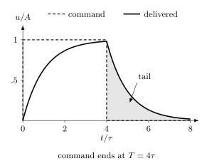
Finite response time rounds the leading edge and produces a tail after the command ends. Here . The total area is preserved by this unit-gain linear filter, but part arrives too late to belong to the nominal gate.
In the commuting resonant model, the rotation angle is the delivered area. At the nominal end time,
The missing area arrives in the tail; the total area out to infinite time is . This does not make the distortion harmless: the next pulse or measurement may begin while the unwanted tail is still present. A different rotation axis or detuning also invalidates a comparison based on area alone.
Comparing the implemented operation with the target
Section titled “Comparing the implemented operation with the target”First check units, supported sample grids, amplitude limits, shared resources and feedback timing. These checks establish that a pulse can run; they do not establish which quantum operation it performs.
For a model prediction, propagate the dispatched samples through the reconstruction and delivery model. Increase the Hilbert-space truncation and reduce the integration time step until the observables of interest converge. Test plausible detuning, gain and spectator states as well as the nominal parameters. Optimal control explains how waveforms are optimized against such models.
For a trace-preserving channel on a -dimensional space, the average gate fidelity relative to a target unitary is
Here is the entanglement fidelity for the maximally mixed input, equivalently the overlap obtained by applying the error channel to one half of a normalized maximally entangled state. Nielsen derives this relation. It does not apply unchanged to projection followed by renormalization: projection onto the qubit space is generally trace decreasing, and input-dependent renormalization is nonlinear. Retain leakage outcomes or report their probability separately.
On the device, repeated-pulse experiments can expose coherent errors, benchmarking tests a specified ensemble of operations, and leakage measurements test escape from the computational space. Check simultaneous operation and use independent data to assess a pulse tuned on earlier measurements. Changed device frequencies, gains or delivery paths can require recalibration; calibration loops describes that process.
Worked example: a sampled quarter turn
Section titled “Worked example: a sampled quarter turn”Consider a target rotation under the resonant effective model
for a duration . A constant-envelope arithmetic model gives
so
At a envelope rate, and the duration occupies
sample intervals. This count refers to forty held sample intervals, not necessarily forty endpoint values in an interpolation scheme. The amplitude must still be converted from a Rabi rate to the calibrated hardware units. The abrupt rectangular envelope is useful for arithmetic but usually poor as a literal command because its broad spectrum excites unwanted dynamics; an actual calibration would commonly use shaped edges or a smooth envelope.
Suppose the delivered gain is high by a fractional amount . In the same simplified model, the angle error is
For a unitary overrotation about the correct axis, the one-qubit average gate fidelity is
With , this model predicts . That number is not a hardware specification. Detuning, leakage, pulse distortion, decoherence, state preparation and measurement, and repeated coherent accumulation are absent. Use the calculation to check units and scale, then measure the implemented operation rather than treating this idealized infidelity as a specification.
Exercises
Section titled “Exercises”1. Pulse area and frequency units
Section titled “1. Pulse area and frequency units”A resonant effective Hamiltonian is . Find the constant needed for an gate in . Explain the error made by entering that number as an angular frequency in radians per second.
Solution
The area condition is
Therefore
The angular frequency is
Entering as though it were under-rotates by a factor of . The numerical field must be typed as cyclic frequency or angular frequency rather than inferred from context.
2. Derive the equatorial rotation axis
Section titled “2. Derive the equatorial rotation axis”Using the carrier and rotating-frame conventions on this page, show that a drive proportional to produces the RWA axis .
Solution
For ,
Multiply by
The terms oscillating at average away under the RWA. The surviving products have averages , giving
Changing the rotating-frame or I/Q sign convention can change the displayed sign, which is why the convention belongs in the target profile.
3. Virtual phase propagation
Section titled “3. Virtual phase propagation”Starting with , a program requests , then a virtual , then another . Which physical phase must the second pulse use? Show how the final frame recovers the desired operation.
Solution
The first pulse has phase zero. After the virtual gate, , so the second physical pulse has phase and axis . With , the physical evolution is . Interpreting the final state in frame gives
which is the requested sequence in right-to-left matrix order. Forgetting the final frame would lose the logical action even if the drive phase were correct. A computational-basis measurement is frame invariant, but a later equatorial measurement must use the transformed axis.
4. Duration-grid policy
Section titled “4. Duration-grid policy”A calibrated pulse has , while a backend requires . Compare rounding to while holding amplitude fixed with rescaling amplitude to preserve area.
Solution
The nearest supported duration is ticks, or . Holding amplitude fixed increases area by
To preserve area in a commuting model, multiply amplitude by
Neither operation is automatically calibration preserving. The first changes angle; the second changes amplitude-dependent shifts, leakage, and spectral response. The correct policy is to select or recalibrate a supported member of the waveform family and record the materialized parameters.
5. Two-channel classical crosstalk
Section titled “5. Two-channel classical crosstalk”At one frequency, suppose
Find the command vector that would produce the target delivered vector in this linear model. Why is this calculation not yet a safe predistortion policy?
Solution
The inverse is
Thus
This is only a single-frequency, linear, perfectly known inversion. A usable policy must consider the full bandwidth, uncertainty, small singular values, amplitude limits, causality, nonlinear response, and experimental validation.
6. Leakage versus conditional fidelity
Section titled “6. Leakage versus conditional fidelity”A pulse leaves probability outside the computational subspace. After projecting onto the computational subspace and renormalizing, the remaining state has squared overlap with a pure target in that subspace. Why is reporting only misleading?
Solution
The reported number conditions on no leakage and discards two percent of the outcomes. Because the target lies entirely in the computational subspace, its unconditional squared overlap is exactly
for this input and final state, even if there are coherences between the subspaces. Leakage can persist, return with uncontrolled phase, affect spectators, and violate the assumptions of later gates or error correction. Report the leakage probability and the conditional in-subspace metric separately.
7. Feedback readiness
Section titled “7. Feedback readiness”An acquisition begins at , integrates for , then takes to classify, and takes another to reach the consuming sequencer. What is the earliest legal start of a conditional pulse?
Solution
The result becomes available at
The pulse may need to start later if its channel has a coarser alignment grid or another resource remains occupied. Starting before is not merely optimistic scheduling; the branch value is unavailable.
8. Gain error and coherent accumulation
Section titled “8. Gain error and coherent accumulation”Using the worked example, compute the small-error infidelity for a gain error. Why can a long sequence reveal a larger effect than this one-gate number suggests?
Solution
The angle error is
Therefore
This is a coherent overrotation. Repetitions with aligned error axes can add angles before probabilities are formed, producing oscillation or roughly quadratic early growth rather than independent stochastic accumulation. Repeated-error amplification is therefore useful for calibration, while a single average number can obscure the mechanism.
9. Account for the pulse tail
Section titled “9. Account for the pulse tail”For the first-order response example with , what fraction of the intended resonant rotation arrives after ? Does waiting another recover the entire angle?
Solution
The fraction arriving after is
After another , the remaining fraction is . An exponential tail never becomes exactly zero at a finite time. Whether this remainder is acceptable depends on the requested operation and what follows it. Waiting also exposes the state to decoherence, which the simple delivery model omits.
10. Equal areas, different pulse order
Section titled “10. Equal areas, different pulse order”Compare an pulse followed by a pulse with their reverse order. Both have area on each axis. Apply the two sequences to .
Solution
The first order gives
where permits a global phase. Reversing the pulses gives
Their Bloch vectors point along and , respectively. Equal area on each control channel does not remove the noncommutativity of and .
References
Section titled “References”- T. Alexander et al., “Qiskit Pulse: Programming quantum computers through the cloud with pulses,” Quantum Science and Technology 5, 044006 (2020), doi:10.1088/2058-9565/aba404.
- A. W. Cross et al., “OpenQASM 3: A broader and deeper quantum assembly language,” ACM Transactions on Quantum Computing 3, 12 (2022), doi:10.1145/3505636.
- D. D’Alessandro, Introduction to Quantum Control and Dynamics, 2nd ed., CRC Press (2021), doi:10.1201/9781003051268.
- S. Gustavsson et al., “Improving quantum gate fidelities by using a qubit to measure microwave pulse distortions,” Physical Review Letters 110, 040502 (2013), doi:10.1103/PhysRevLett.110.040502.
- E. Magesan and J. M. Gambetta, “Effective Hamiltonian models of the cross-resonance gate,” Physical Review A 101, 052308 (2020), doi:10.1103/PhysRevA.101.052308.
- S. Sheldon, E. Magesan, J. M. Chow, and J. M. Gambetta, “Procedure for systematically tuning up cross-talk in the cross-resonance gate,” Physical Review A 93, 060302(R) (2016), doi:10.1103/PhysRevA.93.060302.
- D. C. McKay, C. J. Wood, S. Sheldon, J. M. Chow, and J. M. Gambetta, “Efficient gates for quantum computing,” Physical Review A 96, 022330 (2017), doi:10.1103/PhysRevA.96.022330.
- F. Motzoi, J. M. Gambetta, P. Rebentrost, and F. K. Wilhelm, “Simple pulses for elimination of leakage in weakly nonlinear qubits,” Physical Review Letters 103, 110501 (2009), doi:10.1103/PhysRevLett.103.110501.
- M. A. Nielsen, “A simple formula for the average gate fidelity of a quantum dynamical operation,” Physics Letters A 303, 249–252 (2002), doi:10.1016/S0375-9601(02)01272-0.
- OpenQASM contributors, OpenQASM Language Specification: Pulse-Level Descriptions of Gates and Measurement, current and versioned specification, official specification.
- R. S. Smith, M. J. Curtis, and W. J. Zeng, “A practical quantum instruction set architecture,” (2016), arXiv:1608.03355; see also the current Quil specification.