

Quantum Fourier Transform
The quantum Fourier transform on an -qubit register is the unitary discrete Fourier transform of the register’s amplitudes over the cyclic group . Its short circuit is useful because it turns carefully encoded phase structure into interference, not because it prints a classical table of Fourier coefficients. We will derive its Hadamard–controlled-phase circuit, explain the final bit-reversal swaps, and estimate the error from omitting small rotations.
Here QFT means quantum Fourier transform. The full circuit derivation concerns and the cyclic group ; other finite groups require different encodings and constructions.
Helpful background. Controlled operations explains coherent branch phases; single-qubit gates gives the Hadamard and phase matrices.
Fourier transformation of quantum amplitudes
Section titled “Fourier transformation of quantum amplitudes”Fix an input Hilbert space with computational basis
Using the positive exponential convention, the transform acts on
By linearity,
Those transformed amplitudes are not a freely readable array. One measurement returns one outcome sampled from their squared magnitudes. Recovering phase information or many coefficients requires a separate interference, estimation, or tomography protocol with its own access and repetition costs.
Integers, Endianness, and Fourier Sign
Section titled “Integers, Endianness, and Fourier Sign”Use tensor order
with displayed on the left and on the right. The same convention fixes the integer map:
Thus is the most-significant wire and the least-significant wire. This convention is not “big-endian” or “little-endian” in isolation: the ket order, wire order, memory order, and integer interpretation must be stated together.
Define
This page uses the positive-sign forward transform
so rows are indexed by output and columns by input :
The inverse has the negative exponent,
Some mathematics and software references assign the negative sign to the forward transform. Neither choice changes the content, but silently mixing them turns an intended inverse into a modular-negation operation. Fourier Transform Conventions compares the sign and normalization choices used in other settings.
The QFT as a Finite Unitary
Section titled “The QFT as a Finite Unitary”For two computational-basis columns,
If , every summand is one. Otherwise the ratio obeys but , so the finite geometric sum is
Therefore
Applying the transform twice gives another useful convention check:
Consequently,
These identities check normalization and the modular-negation action, but they do not distinguish the positive- and negative-exponent transforms: both obey them. To test the sign, compare a complex Fourier column or decode a known phase-gradient state, as in the exercises. Wire permutations require a separate check.
The cyclic transform is also a change between the group-element basis of and its character basis. Direct products of finite cyclic groups motivate finite Abelian extensions, but their register layouts and algorithms must be specified separately. General representation theory and non-Abelian Fourier transforms are not silently covered by the power-of-two circuit derived here.
Binary-Fraction Factorization
Section titled “Binary-Fraction Factorization”Write the output integer as
Then the Fourier phase factorizes:
Only the fractional part of matters. Define
For example,
Substituting the binary expansion of into the Fourier sum and distributing the independent sums over gives
The first written factor belongs to and depends only on ; the last belongs to and depends on all input bits. This reversed dependency pattern is why the natural radix-two gate sequence produces a bit-reversed wire order before its final swaps.
For a general superposition the QFT need not be a product state. The factorization above is a column formula for a basis input, used to derive the circuit; linearity then determines the action on arbitrary inputs.
Exact Hadamard–Controlled-Phase Circuit
Section titled “Exact Hadamard–Controlled-Phase Circuit”The phase gates used here are not the site’s Bloch-sphere rotations . Define instead
and
The controlled-phase matrix is symmetric under exchanging its two wires. Naming a control and target is nevertheless useful when following how each input bit contributes to a binary fraction.
Use left-to-right time order in the following construction. For each target wire , starting at and descending to :
- apply to ;
- for , apply with control and target .
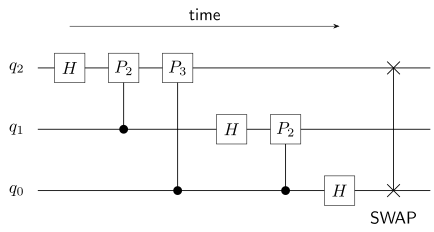
The three-qubit circuit reads left to right, with the most-significant wire. Here and . The final SWAP restores the mathematical output order; omitting it gives .
Finally swap
For a basis input, supplies the leading half-turn and the controlled phases supply the remaining binary-fraction digits. Before the swaps, the phase resides on . After the swaps, it resides on the mathematical output wire required by the product formula.
Let denote the no-swap circuit and define bit reversal by
Then
because .
The exact logical counts in the alphabet are
and
These are counts, not a minimum depth or a native-hardware cost. Universal Gate Sets explains why an abstract continuous phase alphabet and a finite fault-tolerant alphabet are different resource models.
Bit reversal and the inverse circuit
Section titled “Bit reversal and the inverse circuit”Omitting changes the coherent unitary from to . If the register is measured immediately in the computational basis, software may reverse the recorded bits. If a later coherent operation consumes the register, that consumer must be rewritten to absorb or the swaps must be performed. Classical relabeling cannot act retroactively on a coherent state.
The inverse circuit follows from
Thus it reverses the exact forward gate order, conjugates every controlled phase, and retains the declared swap convention. A positive-phase becomes
For a basis input, both the exact circuit and its truncated versions below have uniform computational-basis probabilities. Those probabilities can agree even when the relative phases are wrong. A useful test compares complex amplitudes with the analytic matrix, checks the no-swap result against , and recombines the result with the intended inverse. Unitarity by itself checks only that a circuit is reversible, not that it is the desired Fourier transform.
Approximate QFT and Error Budgets
Section titled “Approximate QFT and Error Budgets”A truncated or approximate quantum Fourier transform (AQFT) drops selected small-angle controlled phases under an explicit error budget. It is a different ideal unitary, not a noise model.
Choose an integer cutoff
and retain only with
This rule keeps all Hadamards and the same declared swaps. It retains
and omits
For an omitted controlled phase with angle
the unitary difference from the identity has operator norm
Insert one omitted gate at a time between otherwise unitary prefixes and suffixes. Unitary invariance of the operator norm and the triangle inequality give the phase-sensitive telescoping bound
provided exact and approximate circuits use identical swaps.
This is a worst-case operator-norm bound with the matrix phase fixed. It is not the fidelity of one selected input, a measured distribution distance, or an algorithm’s success probability. Physical noise and the approximation of retained rotations by a finite gate set are additional errors.
The simpler inequality gives
For , choosing therefore suffices: if the minimum selects , no phase is omitted. Otherwise the retained controlled-phase count is . This is a sufficient cutoff, not necessarily the best one for a particular input or algorithm.
What the short circuit does and does not provide
Section titled “What the short circuit does and does not provide”The exact circuit uses logical gates for qubits. Those counts assume exact controlled rotations and do not include preparing an arbitrary amplitude-encoded input, routing distant qubits, compiling rotations into Clifford+, or extracting many classical coefficients. Gate decomposition treats the synthesis cost. A classical FFT instead accepts a stored array and returns a readable array; these are different input/output tasks.
The coherent transform is used in phase estimation and Shor’s algorithm, whose advantages depend on the rest of the algorithm as well. For a terminal QFT measurement, the semiclassical construction of Griffiths and Niu replaces coherent controlled phases with ordered measurements and classical feedforward. It reproduces the relevant measured output, not a reusable coherent QFT state; mid-circuit measurement explains the distinction.
Worked example: three qubits
Section titled “Worked example: three qubits”Use order and prepare . The circuit applies, in time order,
It uses three Hadamards, three controlled phases and one logical SWAP; the two initial gates used to prepare are separate preparation costs.
For , the analytic output in increasing order is
The binary-fraction form gives the same column as
Every consecutive non-wrapping amplitude ratio is
That phase-sensitive check complements
and
Worked example: truncating a six-qubit transform
Section titled “Worked example: truncating a six-qubit transform”Compare with cutoff , keeping identical final swaps. Both circuits use six Hadamards and three SWAPs. The exact circuit has fifteen controlled phases; the truncated one retains twelve, omitting two gates and one gate. In this logical alphabet the total decreases from to gates.
The exact and retained controlled-phase counts are
The three omissions give
A dense singular-value calculation gives
For , the two nonzero omitted binary-fraction tails are and . The exact-to-truncated column overlap is
and its squared magnitude is
The fidelity is close to one for this column, but only the operator-norm bound establishes a worst-case budget such as . A different input superposition can be more sensitive to coherent phase errors.
The numerical values above follow from building the analytic Fourier matrix and the stated gate sequence, then taking the largest singular value of their difference. A Frobenius norm or largest matrix entry is a different quantity. The overlap can also be checked directly from the product of the two omitted phase factors.
Exercises
Section titled “Exercises”Build F₄ and Check Its Powers
Section titled “Build F₄ and Check Its Powers”Construct the positive-sign four-point transform. Verify unitarity and determine its second and fourth powers.
Solution
With and rows , columns ,
The inner product of columns and is
so . The general power identity gives
In particular,
Applying modular negation twice is the identity, hence .
Factor a Basis Column
Section titled “Factor a Basis Column”Factor in order , then expand the product and match the analytic Fourier column.
Solution
The input bits are . The three binary fractions are
Therefore
For , the product coefficient is
Thus the expanded vector is
which is exactly the column with entries .
Count Exact Logical Resources
Section titled “Count Exact Logical Resources”Count the exact logical QFT gates for . Then translate only the logical SWAP count into CNOTs.
Solution
The formulas give
In the declared abstract alphabet the total is
If each logical SWAP is later decomposed as three CNOTs, report nine CNOTs in place of the three SWAPs. The resulting gate count is seven Hadamards, twenty-one controlled phases, and nine CNOTs. No depth follows without a schedule and connectivity model.
Repair Bit Reversal
Section titled “Repair Bit Reversal”An intended terminal result is on four qubits. Determine the raw no-swap label and state when classical repair is valid.
Solution
The no-swap core applies to the mathematical output:
Interpreted with the original significance convention, the raw label is
Applying restores . If computational-basis measurement is immediate, software may instead reverse the recorded bits and report . That relabeling is invalid before a coherent downstream consumer unless the consumer itself is rewritten to absorb .
Distinguish Forward and Inverse QFT
Section titled “Distinguish Forward and Inverse QFT”Let
Compare the correct inverse with a mistaken application of the forward transform.
Solution
By definition,
The declared inverse therefore gives
Using the positive-sign forward transform instead gives
The wrong sign does not merely add a global phase; it changes the decoded integer.
Truncate a Twelve-Qubit Circuit
Section titled “Truncate a Twelve-Qubit Circuit”For and cutoff , count exact, retained, and omitted controlled phases. Evaluate the telescoping bound and test a operator-norm budget.
Solution
The exact count is
The retained and omitted counts are
The circuit also has twelve Hadamards and six logical SWAPs. Its phase-sensitive telescoping bound is
Because , this bound does not certify the proposed budget. The actual operator norm might be smaller, but that possibility is not a pass; a tighter proof or a direct worst-case calculation is required.
What does uniform readout establish?
Section titled “What does uniform readout establish?”A report observes uniform computational-basis probabilities after transforming a basis state and quotes an logical QFT count. It concludes that the phases and an exponential end-to-end speedup have both been verified. Explain why neither conclusion follows.
Solution
Neither conclusion follows from these observations.
Uniform probabilities establish only
They do not determine the relative phases. Verification needs an inverse-reconstruction test, amplitude-ratio comparison, or another interference-sensitive experiment with declared tolerances.
The count applies only to the abstract transform on coherently encoded qubits. An end-to-end claim must also account for input preparation or oracle access, repetitions, output measurement, classical postprocessing, synthesis, routing, and the success criterion of the surrounding algorithm. No exponential speedup follows from the primitive count alone.
One omitted phase
Section titled “One omitted phase”Take , cutoff and input . Count the omitted gates, calculate the exact operator-norm error, and find the probability that applying the exact inverse to the approximate output returns . Does the approximation meet worst-case budgets and ?
Solution
The exact circuit has four Hadamards, six controlled phases and two SWAPs. The truncated circuit omits only and retains the other eleven logical gates. Because a single gate differs between otherwise identical unitary prefixes and suffixes, norm invariance gives the exact error
It meets the budget and fails the budget. For input , the omitted conditional phase is active and changes one factor of the product output by . The squared overlap of exact and approximate outputs is
This is the probability of returning after the exact inverse. Both forward outputs alone still have uniform computational-basis probabilities. Thus a high selected-state fidelity and a visibly nonzero worst-case error are compatible.
References
Section titled “References”- A. Barenco, C. H. Bennett, R. Cleve, D. P. DiVincenzo, N. Margolus, P. Shor, T. Sleator, J. A. Smolin, and H. Weinfurter, “Elementary Gates for Quantum Computation”, Physical Review A 52, 3457–3467 (1995).
- A. Barenco, A. Ekert, K.-A. Suominen, and P. Törmä, “Approximate Quantum Fourier Transform and Decoherence”, Physical Review A 54, 139–146 (1996).
- R. Cleve, A. Ekert, C. Macchiavello, and M. Mosca, “Quantum Algorithms Revisited”, Proceedings of the Royal Society A 454, 339–354 (1998).
- J. W. Cooley and J. W. Tukey, “An Algorithm for the Machine Calculation of Complex Fourier Series”, Mathematics of Computation 19, 297–301 (1965).
- D. Coppersmith, “An Approximate Fourier Transform Useful in Quantum Factoring”, IBM Research Report RC19642 (1994), arXiv reprint (2002).
- R. B. Griffiths and C.-S. Niu, “Semiclassical Fourier Transform for Quantum Computation”, Physical Review Letters 76, 3228–3231 (1996).
- L. Hales and S. Hallgren, “An Improved Quantum Fourier Transform Algorithm and Applications”, Proceedings of the 41st Annual Symposium on Foundations of Computer Science, 515–525 (2000).
- R. Jozsa, “Quantum Algorithms and the Fourier Transform”, Proceedings of the Royal Society A 454, 323–337 (1998).
- D. Maslov, “Linear Depth Stabilizer and Quantum Fourier Transformation Circuits with No Auxiliary Qubits in Finite Neighbor Quantum Architectures”, Physical Review A 76, 052310 (2007).
- Y. Nam, Y. Su, and D. Maslov, “Approximate Quantum Fourier Transform with O(n log n) T Gates”, npj Quantum Information 6, 26 (2020).
- M. A. Nielsen and I. L. Chuang, Quantum Computation and Quantum Information, 10th anniversary edition, Cambridge University Press (2010).
- P. W. Shor, “Algorithms for Quantum Computation: Discrete Logarithms and Factoring”, Proceedings of the 35th Annual Symposium on Foundations of Computer Science, 124–134 (1994).