

Spintronics
Spintronics studies how spin angular momentum and magnetic order are generated, transported, detected, and used to control electronic or magnetic states. Its central objects are not isolated spins but nonequilibrium spin accumulations, spin-polarized charge currents, pure spin currents, interfacial torques, and magnetization-dependent electrical signals.
A useful device separates four functions:
- generation, by a ferromagnetic contact, optical orientation, the spin Hall effect, or interfacial spin–momentum locking;
- transport, by itinerant electrons, holes, magnons, or collective magnetic order;
- manipulation, by precession, exchange fields, spin–orbit fields, spin-transfer torque, or spin–orbit torque;
- detection, through a ferromagnetic analyzer, inverse charge–spin conversion, magnetoresistance, optical rotation, or magnetic resonance.
Those stages are linked by interfaces. A large bulk polarization or spin Hall conductivity does not guarantee a large device signal if the interface absorbs, depolarizes, reflects, or shunts the relevant current.
Required background. Density and Current Operators supplies spin-current and torque definitions, while Spin–Orbit Coupling in Solids supplies charge–spin conversion mechanisms.
Helpful background. Ferromagnetism provides injection and magnetoresistive context, while Boltzmann Transport provides the semiclassical transport closure.
Spin density, spin current and transport conventions
Section titled “Spin density, spin current and transport conventions”Spin-transport literature uses several quantities all called “spin current.” They are not numerically interchangeable.
Let denote the elementary charge, so an electron has charge . The labels refer to physical electron spin along the chosen quantization axis. A spin-resolved conventional charge-current density has units . Define
The superscript marks the charge-equivalent normalization. Its current polarization is
for transport along . This scalar description is adequate only when a common spin axis remains meaningful. For codirected channel currents, . With opposite flows, that bound need not hold. A pure spin current has but nonzero spin flux, so this ratio is then undefined.
The angular-momentum-current tensor describes flow along spatial direction of spin angular momentum polarized along . Its units are angular momentum per area per time. We define
so also has units . The inverse relation is
For electron transport with quantization axis , a particle-number flux carries charge current . Consequently,
Thus the two charge-equivalent normalizations above differ by a sign, even though they share units. We retain for two-current injection and for angular-momentum conversion. Some authors call the spin current; others use a charge-equivalent quantity and suppress its conversion factor. Every quoted spin Hall angle, interface conductance, or torque efficiency should therefore state both normalization and sign.
For collinear transport, the spin accumulation is the splitting of spin-resolved electrochemical potentials,
For noncollinear transport it becomes a vector in spin space. It has units of energy, not magnetization. A spin density and a spin accumulation are related through the appropriate density of states and susceptibility; they are not identical variables.
Below, is the unit magnetization, is an injected physical-spin direction and is the active magnetic-layer thickness. The electron flow is opposite the conventional current; neither direction alone specifies the spin polarization.
Spin continuity and diffusion
Section titled “Spin continuity and diffusion”For spin density , a local balance equation has the form
where is a coherent torque density and the final term represents a simple spin-flip relaxation model. When the Hamiltonian does not conserve , current and torque can be repartitioned by torque-dipole terms. The measurable content lies in the complete balance law and boundary conditions, not in a current symbol alone.
In a diffusive nonmagnetic conductor, for small departures from equilibrium, isotropic relaxation and a locally linear density–accumulation relation, a common phenomenological equation is
where is a spin-diffusion coefficient, is the Larmor-frequency vector, and is a source. Without precession or a source, each steady component obeys
In one dimension,
Boundary conditions discard the exponentially growing branch in a semi-infinite lead. The diffusion length is therefore not the mean free path: it combines many momentum-scattering events with a slower loss of spin memory.
Define the electron electrochemical voltage by . Then conventional current flows down a voltage gradient, , and
For equal spin-channel conductivities in a nonmagnetic metal,
Equivalently, . Specifying the voltage conversion removes the apparent sign ambiguity.
Spin injection across an interface
Section titled “Spin injection across an interface”Consider a ferromagnet F, a nonmagnetic channel N, and an interface c. In a one-dimensional collinear diffusion model it is useful to compare spin-resistance-area products,
and
Here is the bulk conductivity polarization. Both and have units . For positive spin-channel contact conductances per area and , define
The effective contact spin resistance-area product differs from the bare parallel-channel electrical resistance-area product . In the linear, one-dimensional model with semi-infinite F and N regions, a collinear spin-conserving contact, and no interfacial spin relaxation, Rashba (2000) obtains the injected conventional-current polarization
Here at the interface. These definitions fix the factors in the displayed model; a measured contact voltage can also contain spin-accumulation contributions. The limiting cases are
The first limit is the conductivity-mismatch problem for a transparent ferromagnet–semiconductor contact: the channel’s large spin resistance suppresses injection. A spin-selective tunnel barrier can raise and restore polarization. An arbitrarily resistive barrier is not automatically optimal, because it reduces charge current, signal bandwidth, and impedance matching.
Real interfaces add:
- spin-dependent interface transmission;
- spin-memory loss from interfacial disorder and spin–orbit coupling;
- interface states and Fermi-level pinning;
- current crowding and nonuniform contact geometry;
- magnon-assisted and inelastic channels;
- proximity magnetism and intermixing.
Bulk polarization, contact polarization, and the polarization delivered to the channel are therefore distinct experimental quantities.
Nonlocal detection and Hanle precession
Section titled “Nonlocal detection and Hanle precession”In a lateral nonlocal geometry, one ferromagnet injects current into a nonmagnetic channel while a distant ferromagnet detects voltage in a nominally open circuit. This separation strongly suppresses ordinary charge-voltage backgrounds.
Take an effectively infinite one-dimensional channel, a point injector at and a detector at . Both contacts are sufficiently resistive that spin absorption can be neglected. If the total injected conventional-current difference is , symmetry sends half into each side of the channel. With cross-sectional area ,
Indeed, integrating the spin-current balance across the injector gives , while . The detector reads a conductance-weighted average of the two channel voltages. Relative to the local charge voltage, its open-circuit signal is . Therefore
The polarizations are signed along one common physical-spin axis; reversing one contact reverses this spin signal. For equal polarization magnitudes in the parallel and antiparallel states, the full difference is . Confusing this difference with either signed level produces a factor-of-two error. A semi-infinite channel accepting all injected spin current on one side doubles the level amplitude. Finite contacts and spin absorption require a new boundary-value solution (Takahashi and Maekawa, 2003).
A transverse field rotates the diffusing spins. Define the one-dimensional diffusion kernel
For injection along one spin axis, the ideal Hanle response contains
The kernel sums over all travel times, the exponential accounts for spin relaxation and the cosine records precession. For this ideal infinite channel, introduce
and , using the square root with positive real part. The integral gives
Different travel times precess by different angles, so this is generally not a Lorentzian; at sufficient separation the detected projection can even reverse sign. The parameter becomes order one when
for an isotropic factor. For and this corresponds to about , but the line width also depends on . Reliable extraction of and may require contact-induced relaxation, drift, anisotropic tensors, stray fields, nuclear fields, and magnetic switching to be modeled rather than absorbed into a single Lorentzian.
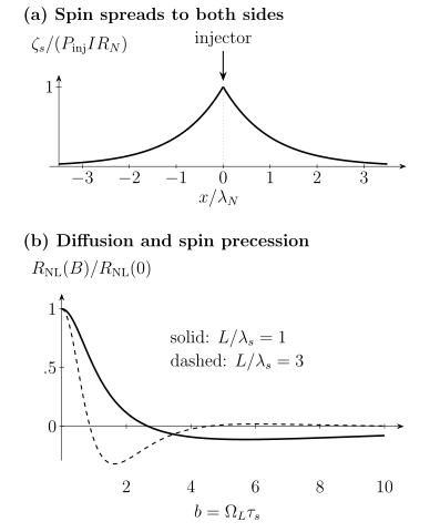
Top: the two sides share the injected spin current, giving in the stated infinite-channel model. Bottom: exact diffusion–precession signals, each divided by its own zero-field value, for and . The more distant detector samples a different travel-time distribution; the sign reversal reflects precession of the measured spin component, not a negative diffusion coefficient.
Giant magnetoresistance
Section titled “Giant magnetoresistance”Giant magnetoresistance (GMR) is the dependence of a metallic multilayer’s resistance on the relative orientation of neighboring magnetic layers. It is a nonequilibrium transport effect, not simply the equilibrium energy that favors one alignment.
The Mott two-current picture begins with weak spin-flip scattering: majority and minority carriers conduct approximately in parallel and experience different resistances. For two identical ferromagnetic layers, let and be the resistance of one layer for spin quantized along its magnetization. In the parallel state,
In the antiparallel state, each channel encounters one majority-like and one minority-like layer, so
Thus
Defining
the same result becomes
This symmetric resistor network explains positive GMR. Different layers or interfaces can have opposite spin asymmetries and can produce inverse GMR; the sign is not a general theorem for every spin valve. Current-in-plane (CIP) and current-perpendicular-to-plane (CPP) geometries sample bulk and interface scattering differently. In CPP structures, the Valet–Fert theory solves spin-dependent diffusion with bulk asymmetries, interface resistances, finite spin-diffusion lengths, and spin accumulation. Layer thicknesses much larger than do not preserve spin contrast throughout their full volume. This loss concerns spin memory; the classical diffusion model does not require electronic phase coherence.
Magnetoresistance mechanisms
Section titled “Magnetoresistance mechanisms”| Effect | State variable controlling resistance | Typical structure |
|---|---|---|
| Anisotropic magnetoresistance (AMR) | angle between current and one magnetic order parameter | single magnetic conductor |
| GMR | relative orientation of metallic magnetic layers | metallic spin valve or multilayer |
| Tunneling magnetoresistance (TMR) | relative orientation across a tunnel barrier | magnetic tunnel junction |
| Spin Hall magnetoresistance | spin reflection and absorption at a spin–orbit-metal/magnet interface | bilayer |
| Colossal magnetoresistance (CMR) | coupled magnetic, electronic, and structural state | correlated magnetic oxide |
For an ideal spin-conserving tunnel junction, Jullière’s model gives
where and are tunneling density-of-states polarizations. Crystalline symmetry filtering, barrier defects, bias, temperature, magnons, and interface resonances can invalidate this simple density-of-states formula.
Charge–spin conversion
Section titled “Charge–spin conversion”Spin–orbit coupling permits reciprocal conversion between longitudinal charge flow and transverse spin flow. To make signs explicit, suppose a charge current flows along , spin angular momentum flows along , and its polarization is . We define the sign of the spin Hall angle by
Changing the interface normal or choosing electron flow instead of conventional current changes the verbal handedness. The tensor relation, axes, and sign convention should accompany every number.
The intrinsic Berry-curvature contribution, skew scattering, side jump, and the conventional spin-current operator are developed in Spin–Orbit Coupling in Solids. At the device level, a measured conversion also depends on layer thickness , spin-diffusion length , resistivity , effective spin-mixing conductance , interface transparency and current shunting.
A fitted torque efficiency is therefore not automatically the intrinsic bulk spin Hall angle.
The inverse spin Hall effect converts an injected spin flux into a transverse charge signal. Onsager reciprocity constrains direct and inverse linear-response coefficients after all time-reversal-odd variables, especially magnetization, are transformed consistently. It does not excuse ignoring open-circuit boundary conditions or sign conventions.
At a two-dimensional inversion-asymmetric interface, the Edelstein effect produces a nonequilibrium spin accumulation from an in-plane electric field. The inverse Edelstein response converts a nonequilibrium interfacial spin density into a two-dimensional charge current. When the input is an injected spin flux, spin relaxation and escape determine the resulting density and the measured conversion length. This interfacial spin density is not the same object as a bulk transverse spin Hall current, even though both can generate similar torques.
Spin pumping and interfacial mixing
Section titled “Spin pumping and interfacial mixing”A precessing magnet can emit spin angular momentum into an adjacent conductor. For a slowly varying unit magnetization, the pumped angular-momentum current per area is
The spatial flow direction here is outward from the ferromagnet; the vector components specify spin polarization. The real and imaginary parts and use the dimensionless-channel convention per area, with units , not electrical conductance per area. A receiving conductor can develop spin accumulation and send angular momentum back, reducing the net exported flux (Tserkovnyak et al., 2002).
Neglecting the imaginary part or its small gyromagnetic-ratio correction, the net interfacial angular-momentum loss adds Gilbert damping:
Here is real and is in . With interfacial spin-memory loss, this damping parameter measures total angular momentum lost by the magnet; it is not necessarily the conductance for spin reaching the bulk receiving layer. Inverse spin Hall voltage or a nonlocal detector samples that transmitted part. Ultrafast terahertz emission can also detect spin flux, but the slow-precession formula above does not by itself describe femtosecond nonequilibrium transport. A linewidth increase alone is not unique proof of spin pumping: two-magnon scattering, radiative damping, eddy currents, inhomogeneous broadening, and magnetic proximity effects require controls.
Spin pumping and spin-transfer torque are reciprocal interfacial processes. One exports angular momentum from a moving magnet; the other absorbs angular momentum from an incident nonequilibrium spin distribution.
Spin-transfer and spin–orbit torques
Section titled “Spin-transfer and spin–orbit torques”The Landau–Lifshitz–Gilbert equation with current-induced torques can be written
For a spin flux polarized along and absorbed by a uniform magnetic layer, the leading angular structures are
and
The first is called damping-like because its symmetry can oppose or reinforce Gilbert damping for a suitable trajectory. The second has the symmetry of precession about an effective field. The names describe vector form, not a unique microscopic origin.
Define a signed magnetization-torque efficiency through
The efficiency includes conversion, transmission, and the sign appropriate to this equation for magnetization. For example, if the transverse angular momentum absorbed into an electron-spin ferromagnet per area and time is , then , with the angular-momentum density, gives . A signed magnetization-torque efficiency must therefore not be identified silently with the angular-flux conversion ratio.
For a spin valve, is the physical injected-spin direction set by a polarizing magnetic layer, and the torque is usually called spin-transfer torque. In a spin–orbit bilayer, can be generated by the spin Hall or Edelstein effect and the torque is usually called spin–orbit torque.
In a smoothly varying magnetic texture, current within the magnet also produces adiabatic and nonadiabatic torques:
The drift parameter is proportional to current polarization, and is a nonadiabatic coefficient. This continuum form assumes a texture smooth on microscopic transport scales.
For a collinear polarizer and a nearly circular small-amplitude mode about a uniform equilibrium, the linear antidamping threshold follows by balancing spin torque against damping. With the mode field scale,
The required polarity supplies antidamping for the chosen state. Crossing this threshold can produce sustained oscillation or reversal; it does not guarantee switching. In particular, a perpendicular magnet with in-plane spin polarization generally has a different spin–orbit-torque switching problem, including symmetry breaking and possible static loss of stability. Its threshold need not scale as . Nonuniform reversal, pulse length, heating and the desired error probability further affect actual write currents.
Materials and devices
Section titled “Materials and devices”Different devices need different combinations of transport length, readout contrast and write efficiency:
| Platform | Main function | Useful attributes | Frequent limitation |
|---|---|---|---|
| Metallic ferromagnet/nonmagnet | injection, GMR, spin torque | high current density, mature interfaces | short , Joule heating |
| Magnetic tunnel junction | TMR readout, STT switching | large resistance contrast, nonvolatility | barrier defects, write stress, stochastic switching |
| Heavy spin–orbit metal or semimetal | spin Hall generation and inverse detection | efficient charge–spin conversion | shunting, resistive loss, interface uncertainty |
| Semiconductor or two-dimensional channel | gate control, long-distance transport | tunable density and spin–orbit coupling | contact mismatch, disorder, environmental sensitivity |
| Magnetic insulator | magnon transport, spin pumping | negligible electronic charge current in magnet | interface conversion and magnon relaxation |
| Antiferromagnet or ferrimagnet | fast dynamics, compensated or low-moment operation | weak stray fields, rich torque symmetry | readout, domain control, material variability |
Read and write architectures
Section titled “Read and write architectures”Metallic spin valves and GMR multilayers enabled compact magnetic-field sensors and hard-disk read heads. A magnetic tunnel junction uses TMR to distinguish a free layer from a reference layer. In spin-transfer-torque MRAM, the current used to read the tunnel junction also passes through it during writing. In many spin–orbit-torque designs, a lateral current in an adjacent layer writes a magnetic element while the tunnel junction provides a separate read path.
The magnetic energy barrier must satisfy
large enough for retention, while write torque must still cross the barrier quickly and reliably. Magnetic Anisotropy explains this barrier and its thermally activated crossing. Lowering reduces write cost but also retention; increasing damping can accelerate settling while raising antidamping current.
“Low power” is not a material property. Energy per successful operation must include line resistance, pulse duration, capacitive loading, write errors, standby leakage, peripheral circuitry, and the cost of maintaining the required field or symmetry breaking.
Interpreting a measured spin signal
Section titled “Interpreting a measured spin signal”Electrical spin signals must be compared with ordinary charge transport and the magnetic state. Reversing one injector or detector tests the predicted spin parity, while a transverse-field Hanle scan tests precession. Neither check alone excludes stray-field Hall signals, thermoelectric backgrounds or contact-induced relaxation. Geometry and contact absorption belong in the transport fit.
For torque measurements, spin-torque ferromagnetic resonance and harmonic Hall analysis separate angular responses only within a model. Oersted fields, anomalous Nernst voltages, spin Seebeck response, planar Hall mixing and current crowding can imitate some torque symmetries. Independent resistivity, magnetic thickness, damping and anisotropy measurements reduce the ambiguity. Pumping and reciprocal detection provide complementary checks, with interfacial spin loss treated explicitly.
Exercises
Section titled “Exercises”1. Diffusion from a narrow injector
Section titled “1. Diffusion from a narrow injector”A one-dimensional nonmagnetic channel receives a localized steady spin source at . Away from the source,
and must remain finite as . Find the profile if . What detector spacing reduces the signal to of its interfacial value?
Solution
On the right, finiteness removes the growing exponential; on the left it removes the exponential that grows toward negative infinity. Continuity at the injector gives
The ratio at a detector a distance away is
It equals at
The derivative jumps at because the idealized injector is a delta-function source. A finite-width injector smooths that cusp.
2. Two-current GMR
Section titled “2. Two-current GMR”Derive the parallel and antiparallel resistances of the symmetric two-layer model and show that .
Solution
In the parallel state, the two channel resistances are and in parallel:
Therefore
In the antiparallel state, each channel has series resistance , and the two equal channels are in parallel:
Their difference is
Equality holds only when the two spin channels scatter identically. The proof applies to the stated resistor model, not automatically to every nonlinear or quantum-coherent device.
3. Charge-equivalent and angular-momentum currents
Section titled “3. Charge-equivalent and angular-momentum currents”A bilayer carries and has in the convention . Find and .
Solution
The charge-equivalent spin-current density is
The angular-momentum-current density is
Using ,
Since equals angular momentum per unit time, this is equivalently angular momentum per area per time. The numerical values differ by the dimensional factor ; neither should be quoted without units. For physical electron-spin channels quantized along , the corresponding conventional-current difference is , with the opposite sign.
4. Antidamping threshold and retention
Section titled “4. Antidamping threshold and retention”Take , , , and retain a constant damping-like coefficient . Linearize the Gilbert equation about . Which sign and magnitude of destabilize this state? How does the result relate to reducing the anisotropy of a perpendicular uniaxial memory element?
Solution
For , let and . The linearized equation is
Its growth rates are
Positive stabilizes this particular state; negative makes the real part positive. Substitution of the defined torque efficiency yields the displayed current threshold. This is a local stability calculation, not a proof of deterministic reversal.
For an ideal uniaxial macrospin with , the threshold magnitude is proportional to . Reducing lowers this threshold but also lowers and exponentially shortens thermal retention. A noncollinear torque geometry or nonuniform reversal requires a different stability calculation.
References
Section titled “References”- M. N. Baibich, J. M. Broto, A. Fert, F. Nguyen Van Dau, F. Petroff, P. Etienne, G. Creuzet, A. Friederich, and J. Chazelas, “Giant magnetoresistance of (001)Fe/(001)Cr magnetic superlattices,” Physical Review Letters 61, 2472–2475 (1988), doi:10.1103/PhysRevLett.61.2472.
- G. Binasch, P. Grünberg, F. Saurenbach, and W. Zinn, “Enhanced magnetoresistance in layered magnetic structures with antiferromagnetic interlayer exchange,” Physical Review B 39, 4828–4830 (1989), doi:10.1103/PhysRevB.39.4828.
- A. Brataas, G. E. W. Bauer, and P. J. Kelly, “Non-collinear magnetoelectronics,” Physics Reports 427, 157–255 (2006), doi:10.1016/j.physrep.2006.01.003.
- F. J. Jedema, A. T. Filip, and B. J. van Wees, “Electrical spin injection and accumulation at room temperature in an all-metal mesoscopic spin valve,” Nature 410, 345–348 (2001), doi:10.1038/35066533.
- M. Jullière, “Tunneling between ferromagnetic films,” Physics Letters A 54, 225–226 (1975), doi:10.1016/0375-9601(75)90174-7.
- A. D. Kent and D. C. Worledge, “A new spin on magnetic memories,” Nature Nanotechnology 10, 187–191 (2015), doi:10.1038/nnano.2015.24.
- A. Manchon, J. Železný, I. M. Miron, T. Jungwirth, J. Sinova, A. Thiaville, K. Garello, and P. Gambardella, “Current-induced spin-orbit torques in ferromagnetic and antiferromagnetic systems,” Reviews of Modern Physics 91, 035004 (2019), doi:10.1103/RevModPhys.91.035004.
- D. C. Ralph and M. D. Stiles, “Spin transfer torques,” Journal of Magnetism and Magnetic Materials 320, 1190–1216 (2008), doi:10.1016/j.jmmm.2007.12.019.
- E. I. Rashba, “Theory of electrical spin injection: Tunnel contacts as a solution of the conductivity mismatch problem,” Physical Review B 62, R16267–R16270 (2000), doi:10.1103/PhysRevB.62.R16267, author preprint.
- S. Takahashi and S. Maekawa, “Spin injection and detection in magnetic nanostructures,” Physical Review B 67, 052409 (2003), doi:10.1103/PhysRevB.67.052409.
- Y. Tserkovnyak, A. Brataas, and G. E. W. Bauer, “Enhanced Gilbert damping in thin ferromagnetic films,” Physical Review Letters 88, 117601 (2002), doi:10.1103/PhysRevLett.88.117601.
- Y. Tserkovnyak, A. Brataas, G. E. W. Bauer, and B. I. Halperin, “Nonlocal magnetization dynamics in ferromagnetic heterostructures,” Reviews of Modern Physics 77, 1375–1421 (2005), doi:10.1103/RevModPhys.77.1375.
- T. Valet and A. Fert, “Theory of the perpendicular magnetoresistance in magnetic multilayers,” Physical Review B 48, 7099–7113 (1993), doi:10.1103/PhysRevB.48.7099.
- I. Žutić, J. Fabian, and S. Das Sarma, “Spintronics: Fundamentals and applications,” Reviews of Modern Physics 76, 323–410 (2004), doi:10.1103/RevModPhys.76.323.