

Magnetic Anisotropy
Magnetic anisotropy is the dependence of a magnetic system’s free energy on the orientation of its order parameter relative to the crystal, sample, interfaces, strain, or other fixed spatial structure. An easy axis is an orientation that minimizes this free energy; an easy plane is a continuous set of minimizing directions within a plane. The corresponding maxima are hard directions.
Anisotropy turns a rotationally symmetric magnetic model into a material. It selects the direction of a ferromagnetic magnetization or antiferromagnetic Néel vector, gaps some spin-wave modes, controls coherent-rotation fields, contributes to domain-wall width and energy, and competes with dipolar and Dzyaloshinskii–Moriya interactions to organize textures.
The phrase covers several mechanisms that must not be conflated:
- magnetocrystalline anisotropy, generated when spin–orbit coupling ties spin and orbital moments to crystal symmetry;
- single-ion anisotropy, a local low-energy representation of crystal-field and spin–orbit physics;
- anisotropic exchange, including symmetric exchange and antisymmetric Dzyaloshinskii–Moriya coupling;
- shape anisotropy, the orientation dependence of magnetostatic self-energy;
- surface and interface anisotropy, allowed because translation and inversion symmetries differ from the bulk;
- magnetoelastic anisotropy, generated by strain and magnetostriction.
Required background. Spin–Orbit Coupling in Solids supplies the microscopic spin–orbital bridge, while Exchange Interactions supplies exchange-tensor and bond conventions.
Helpful background. Ferromagnetism and Antiferromagnetism provide the uniform and staggered order-parameter branches.
Directional magnetic energy and field conventions
Section titled “Directional magnetic energy and field conventions”We describe a fixed-length magnetization by the unit vector and use for energy or free energy per volume in SI units. A crystal coefficient, a surface energy per area and an energy per ion are different quantities; their conversion requires the sample thickness or volume per ion. At finite temperature the relevant orientation function is a free energy, so its coefficients need not equal zero-temperature energy differences.
The field in a Zeeman term is the applied field in amperes per meter. Magnetostatic self-energy is included separately, either explicitly or through a stated effective anisotropy. Below, SI demagnetizing factors satisfy ; Gaussian tables whose sum is require conversion.
For a ferromagnet in zero applied field, reversing all moments is a time-reversal-related state. The orientation energy therefore satisfies
unless another fixed time-reversal-odd object is present. Crystal anisotropy expansions consequently begin with even powers of . Dzyaloshinskii–Moriya terms can be linear in spatial gradients while remaining even under simultaneous reversal of every spin.
Symmetry before coefficients
Section titled “Symmetry before coefficients”At quadratic order, the most general orientation energy of a unit axial vector is
where only the symmetric part of contributes. Adding a multiple of the identity shifts every orientation by the same constant because . The physically relevant quadratic anisotropy is therefore the traceless part.
For every spatial symmetry represented by , the tensor must satisfy
Diagonalizing identifies its principal directions. In a uniaxial environment, two eigenvalues coincide and the remaining eigenvector defines the symmetry axis. In a fully cubic environment, symmetry forces to be proportional to the identity, so quadratic orientation dependence is only a constant. Cubic magnetocrystalline anisotropy begins at fourth order.
This invariant method is more reliable than guessing an “anisotropy axis” from a drawing. For an antiferromagnet, apply the magnetic space group to the Néel vector and any weak ferromagnetic moment together. A crystallographic axis need not be magnetically easy, and symmetry determines allowed terms rather than their signs or magnitudes.
Easy axes, planes, and cones
Section titled “Easy axes, planes, and cones”Let be the angle from a uniaxial crystal axis . A common expansion is
where contains symmetry-allowed in-plane harmonics. First set , so every azimuth is equivalent. With in this convention:
- gives an easy axis along ;
- gives an easy plane perpendicular to .
Another common convention writes , reversing the verbal sign rule. A sign without the defining equation is not useful.
Higher-order terms can create an easy cone. Setting
gives
For and
the minimum lies at
Thus the sign of one coefficient need not identify the actual easy direction. Nonzero in-plane harmonics can select discrete directions from the ideal plane or cone; continuous degeneracy requires their absence.
Cubic crystals
Section titled “Cubic crystals”For direction cosines
the leading cubic anisotropy is
The high-symmetry values are
For , minimizing over all unit vectors gives when and when . With higher-order invariants, comparing only three high-symmetry directions is not a general minimization proof; other stationary directions must also be tested.
Anisotropy field
Section titled “Anisotropy field”For a single-domain uniaxial ferromagnet with a transverse field,
where includes any local shape contribution and is the applied field, coherent rotation reaches the hard direction at
Equivalently,
is not generally the coercive field. Coercivity depends on nucleation, defects, pinning, thermal activation, domain-wall motion, sweep protocol, and sample history. Equality occurs only in restricted coherent-rotation models.
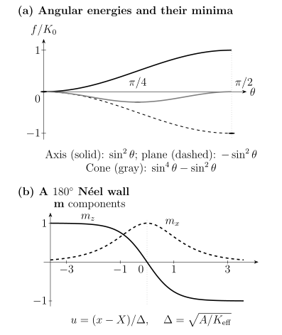
Top: , and have their minima at , and , respectively. Bottom: the exact wall has and , where and . The opposite Néel chirality reverses ; the interfacial coupling defined below favors the plotted chirality for .
Crystal-field and spin–orbit mechanisms
Section titled “Crystal-field and spin–orbit mechanisms”Electrostatic crystal fields act primarily on orbital charge distributions. Spin–orbit coupling then ties those orbitals to spin or total angular momentum, producing an orientation-dependent energy. Because the effect compares nearly equal total energies, its scale can be much smaller than the spin–orbit matrix elements that generate it.
Single-ion representation
Section titled “Single-ion representation”For a dimensionless local spin , a frequently used effective Hamiltonian is
With this sign convention and , favors large , while favors small . The classical fixed-length limit is easy-axis-like or easy-plane-like, respectively. A quantum ion need not carry a classical arrow: for and , the isolated ground state is the nonmagnetic singlet. Exchange can change the many-ion ground state. The term removes in-plane rotational symmetry.
For ,
The quadratic onsite term is therefore a constant and cannot split an isolated Kramers doublet at zero field. An effective spin- can still have an anisotropic tensor and anisotropic exchange. A reported zero-field splitting for a genuine two-state Kramers system indicates that additional states, time-reversal breaking, or an inappropriate effective model have been hidden.
For rare-earth and actinide ions, the crystal field within a fixed multiplet is often expanded in Stevens operators:
Only terms allowed by the site point group survive. The coefficients depend on ligand geometry, screening, covalency, and radial matrix elements. A non-Kramers ion can acquire a singlet or split non-Kramers doublet under lower symmetry, whereas a Kramers doublet remains degenerate until time reversal is broken.
Itinerant magnetocrystalline anisotropy
Section titled “Itinerant magnetocrystalline anisotropy”In an itinerant magnet, rotating the magnetization changes spin–orbit hybridization throughout the occupied band structure. For nondegenerate independent-electron levels with unchanged occupations, second-order perturbation theory gives
The magnetocrystalline anisotropy energy is a difference such as
Small occupied–unoccupied separations can enhance the effect, but a vanishing denominator signals failure of nondegenerate perturbation theory, not an infinite physical anisotropy. Near a crossing, diagonalize the coupled states. In a metal, also track occupation and chemical-potential changes at fixed electron number. These features make anisotropy sensitive to filling, strain, interfaces and numerical convergence.
Under a restricted set of assumptions—large exchange splitting, weak spin–orbit coupling, negligible spin-flip terms and a filled majority band so that minority-spin virtual transitions dominate—the Bruno relation connects anisotropy to orbital-moment anisotropy:
Here is the spin–orbit energy scale and is the orbital magnetic moment along the magnetization; the moment and energy must use the same per-atom or per-cell normalization. The relation is a useful diagnostic (Bruno, 1989), not an identity for arbitrary multiorbital, strongly relativistic, antiferromagnetic or correlated materials.
Magnetoelastic coupling
Section titled “Magnetoelastic coupling”For a cubic ferromagnet, a leading magnetoelastic energy is
Strain can therefore change the easy direction even if the unstrained crystal constants are fixed (Sander, 1999). Conversely, rotating the magnetization can change the equilibrium strain: magnetostriction and magnetoelastic anisotropy are reciprocal descriptions of the same coupling.
Surfaces and interfaces
Section titled “Surfaces and interfaces”At a surface, missing neighbors, altered hybridization, relaxation, electric fields, and reduced point-group symmetry permit anisotropy terms absent or equivalent in the bulk. A leading surface contribution is an energy per area,
where is interface area and positive favors the surface normal in this convention. For two inequivalent interfaces, the film contribution is
not automatically .
The atomic-scale origin may be described through broken-bond pair anisotropy, interface-modified orbital moments, strain, charge transfer, or hybridization with a heavy adjacent layer. Thickness scaling can separate area-like and volume-like terms only over a range where the structure, magnetization, and interface chemistry remain comparable. Voltage control of anisotropy can reflect electrostatic occupation changes, ionic motion, piezoelectric strain, or redox chemistry; a gate dependence alone does not identify which mechanism operates.
Shape anisotropy and demagnetizing fields
Section titled “Shape anisotropy and demagnetizing fields”Both spatial variation inside a magnet and its boundary can produce a magnetostatic field. Even a uniformly magnetized finite body generally has a nonzero . With extended by zero outside the sample, the field satisfies
Writing gives
The magnetostatic self-energy can be expressed as
For a uniformly magnetized ellipsoid, the internal field is uniform (Osborn, 1945):
Along the principal axes,
The easiest shape direction has the smallest . Useful limits are:
The film and needle entries are ideal infinite-aspect-ratio limits. For a finite rectangular prism, is nonuniform and a single demagnetizing tensor is at best an averaged description tied to a specified magnetization state.
Perpendicular anisotropy in a film
Section titled “Perpendicular anisotropy in a film”Suppose a film has a volume magnetocrystalline contribution , two equivalent interface contributions per area, thickness , and uniform . Taking positive to favor the film normal,
favors perpendicular magnetization, whereas favors the film plane in the uniform approximation. The dependence is a useful interface diagnostic, but roughness, dead layers, asymmetric interfaces, thickness-dependent , strain relaxation, and higher-order terms can spoil a straight-line extraction.
Shape anisotropy is often called a dipolar anisotropy. It is not a local crystal constant. A sample can reduce its magnetostatic energy by forming domains, so the direction observed in a multidomain image is not automatically the intrinsic uniform-state easy axis.
Anisotropic exchange and Dzyaloshinskii–Moriya coupling
Section titled “Anisotropic exchange and Dzyaloshinskii–Moriya coupling”A general bilinear pair interaction can be decomposed as
where is symmetric and traceless. Reversing the declared bond orientation changes
An inversion center at the bond midpoint forces . Other point-group operations constrain its allowed direction. Broken inversion is necessary but not sufficient for an arbitrary Dzyaloshinskii–Moriya vector.
For a uniform collinear state,
so Dzyaloshinskii–Moriya coupling does not by itself define the easy direction of that state. It favors canting and handed spatial variation. Symmetric anisotropic exchange can contribute directly to the energy of a collinear orientation.
Continuum invariants
Section titled “Continuum invariants”For a unit magnetization field , a representative micromagnetic functional is
Here is the magnetic sample, is exchange stiffness in joules per meter, and is the local uniaxial anisotropy density before including magnetostatic shape energy. The densities and have units of joules per cubic meter. For a film uniform through its thickness, the two equivalent interfaces above can be included through .
The full nonlocal magnetostatic energy is
where and , with extended by zero outside the sample. In the local thin-film approximation, replacing this energy by its shape-anisotropy contribution gives , up to a magnetization-independent constant. That replacement and the full are alternative descriptions: adding the full to an anisotropy already containing this shape term would count it twice.
Two common Dzyaloshinskii–Moriya densities are
for an isotropic chiral bulk crystal, and
for an ideal interface with polar normal . The gradients in the interfacial expression are in the film plane. In these three-dimensional energy densities, has units of joules per square meter. Integrating through a uniform film of thickness gives a two-dimensional coefficient in joules per meter; neither is the surface-anisotropy coefficient . Signs depend on coordinate and chirality conventions. Using a bulk invariant for an interface, or vice versa, changes the preferred texture.
From anisotropy to magnetic textures
Section titled “From anisotropy to magnetic textures”Exchange penalizes rapid variation, anisotropy penalizes departure from preferred directions, magnetostatics rewards flux closure, and Dzyaloshinskii–Moriya coupling rewards a selected twist. Their competition creates domains, walls, spirals, bubbles, and skyrmions.
Exchange and anisotropy lengths
Section titled “Exchange and anisotropy lengths”For the following local thin-film benchmarks, take and neglect the residual nonlocal magnetostatic energy after absorbing the local shape term. This is the approximation used for the analytic wall results by Rohart and Thiaville (2013). Two useful scales are
compares exchange with uniaxial anisotropy; compares exchange with magnetostatic energy. They answer different questions and should not both be called “the exchange length” without definition.
For a one-dimensional wall with
and energy per wall area
the minimizing profile is
Its energy is
Some authors call the wall width; others define a geometric width . Numerical values should always state the convention.
The chirality sign follows directly from the interfacial invariant. Allow a constant wall azimuth and write
For the increasing profile above,
Thus favors and favors . This term is a boundary contribution for constant , so it changes the infinite-wall energy without changing its minimizing width in this ideal model. Minimizing over chirality gives
The nominal threshold at which this isolated-wall expression reaches zero is
Above this threshold, inserting well-separated favored walls can lower the energy of an infinite uniform state, leading toward a modulated ground state. This is an energetic comparison, not a universal small-amplitude instability criterion: the perpendicular uniform state can remain a local minimum. Finite edges acquire Dzyaloshinskii–Moriya boundary conditions, and dipolar fields, applied field and confinement change the comparison. Skyrmions and Magnetic Textures develops the resulting topology, stability and dynamics.
Bloch and Néel walls are distinguished by the plane in which rotates. In a bulk uniaxial magnet, magnetostatic geometry often decides between them. At an inversion-asymmetric interface, Dzyaloshinskii–Moriya coupling can select a Néel wall and one handedness. Observing one wall type therefore constrains an energy competition; it does not measure one coefficient without the others.
Ferromagnets and antiferromagnets
Section titled “Ferromagnets and antiferromagnets”In a ferromagnet, anisotropy acts on and is often measured through torque, resonance, hard-axis saturation, or orientation-dependent total energy. Magnetostatic shape effects can be comparable to or larger than magnetocrystalline terms.
In a collinear antiferromagnet, the principal orientation variable is the Néel vector
The net magnetization can be nearly zero while spin–orbit coupling still produces a substantial . Shape anisotropy of the net moment may then be weak, but dipolar coupling between sublattices, weak ferromagnetic canting, and surface moments can remain relevant.
Exchange and anisotropy fields also enter differently. In a simple two-sublattice easy-axis antiferromagnet with
the spin-flop scale behaves schematically as
The large exchange field amplifies a modest anisotropy in the resonance and reorientation scales. Exact coefficients depend on field direction, sublattice moments, anisotropy terms, and convention.
Temperature and effective parameters
Section titled “Temperature and effective parameters”An anisotropy constant inferred at finite temperature is a free-energy coefficient after thermal electronic, spin, lattice, and possibly domain degrees of freedom have been integrated out. It need not equal a zero-temperature energy difference.
For localized single-ion anisotropy under restrictive assumptions, the Callen–Callen relation suggests
For a leading second-rank uniaxial term this gives the familiar cubic power. The relation is not universal for itinerant magnets, two-ion anisotropy, antiferromagnets, interfaces, or temperatures near a phase transition. Competing terms with different temperature dependences can drive a spin-reorientation transition.
Energy barriers and switching
Section titled “Energy barriers and switching”For a single-domain particle with two equivalent uniaxial minima and no applied field, the ideal coherent-rotation barrier is
The dimensionless thermal-stability factor is
In a simple Néel–Brown picture, the mean reversal time is approximately
in the high-barrier, thermally activated regime, with an attempt time determined by damping, curvature of the energy landscape, and field (Brown, 1963). This exponential sensitivity is why anisotropy is central to magnetic recording and nanomagnet stability. Spintronics develops how retention competes with spin-torque write current in device architectures.
Real particles can reverse by curling, edge nucleation, domain-wall propagation, or collective modes with barriers below . The relevant barrier is the lowest free-energy saddle compatible with geometry and observation time. A blocking temperature is therefore protocol dependent, not a thermodynamic phase boundary.
Experimental and computational inference
Section titled “Experimental and computational inference”Torque and angular scans
Section titled “Torque and angular scans”The magnetic torque is
where the derivative denotes rotation in the specified plane. For ,
Angular harmonics identify allowed symmetry terms, but background torque from the holder, field misalignment, incomplete saturation, and demagnetizing geometry must be controlled.
Magnetometry and resonance
Section titled “Magnetometry and resonance”Hard-axis magnetization can estimate only if the sample rotates coherently or the domain process is modeled. Ferromagnetic resonance accesses derivatives of the free energy around equilibrium; converting resonance fields to requires the correct sample geometry, , tensor, field orientation, and mode assignment.
Antiferromagnetic resonance, inelastic neutron scattering, and terahertz spectroscopy can infer anisotropy from mode gaps and field evolution. Spin Waves and Magnons explains why energies, intensities, polarization, and linewidths should be fitted together.
Magnetic imaging reveals domains and walls, not an anisotropy constant by itself. Extracting , , and from one measured wall width is underdetermined unless independent constraints and the appropriate wall model are supplied. X-ray magnetic circular dichroism can constrain spin and orbital moments, while linear dichroism can be sensitive to antiferromagnetic orientation; their sum rules, projection geometry, and multiplet assumptions must be stated.
First-principles calculations
Section titled “First-principles calculations”A robust magnetocrystalline-anisotropy calculation should:
- converge total-energy differences with respect to momentum mesh, basis, smearing, and self-consistency;
- state whether it uses fully self-consistent energies, a force theorem, or a torque method;
- use the same structure, electron number, and numerical settings for each orientation;
- separate bulk, surface, dipolar, and strain contributions when comparing with experiment;
- test sensitivity to correlation parameters and band filling near avoided crossings;
- report energy per atom or cell and the conversion to per volume or area.
The anisotropy energy may be microelectronvolts per atom even when individual electronic energies are electronvolts. Convergence of the total energy alone does not guarantee convergence of their small orientation difference.
Exercises
Section titled “Exercises”1. Easy-axis, easy-plane, and easy-cone regimes
Section titled “1. Easy-axis, easy-plane, and easy-cone regimes”For
classify the minimum as varies.
Solution
Set . Then
If , the unconstrained stationary point is at , so the minimum is : an easy axis.
If
the stationary point lies inside the interval:
This gives an easy cone at .
If , the unconstrained minimum lies at , so the constrained minimum is : an easy plane. At the equalities, neighboring regimes meet continuously.
2. Thickness-driven reorientation
Section titled “2. Thickness-driven reorientation”For
find the critical thickness at which the uniform easy direction changes. State the condition for a positive result, and evaluate it for , and .
Solution
Set :
For , a positive finite requires
For the specified values, , giving . The interface term favors perpendicular magnetization below this thickness; the combined volume and demagnetizing terms favor the plane above it. This compares uniform states. Domains, thickness-dependent , unequal interfaces and strain can shift or preempt the simple reorientation.
3. Domain-wall profile and energy
Section titled “3. Domain-wall profile and energy”Minimize
subject to and .
Solution
The Euler–Lagrange equation is
Multiplying by and using the boundary conditions gives the first integral
Choosing the increasing solution,
Integration yields
Using equality of the exchange and anisotropy densities,
4. Chiral-wall energy and local stability
Section titled “4. Chiral-wall energy and local stability”In the ideal interfacial model,
Find . Does the perpendicular uniform state necessarily become unstable to every small perturbation above this threshold? Test a periodic disturbance with fixed wall azimuth.
Solution
Solving gives
The favored isolated wall has negative energy for , so an infinite uniform state is no longer the global ground state. But for the periodic small-angle disturbance, the chiral term integrates to zero, and the energy change per length is
The uniform state can therefore remain locally stable even when a finite-amplitude modulated configuration is energetically preferable. The threshold alone does not select a spiral, stripe or skyrmion state in a finite real sample; field, nonlocal dipolar energy and boundaries must also be included.
References
Section titled “References”- W. F. Brown, Jr., Micromagnetics, Wiley (1963).
- W. F. Brown, Jr., “Thermal Fluctuations of a Single-Domain Particle,” Physical Review 130, 1677–1686 (1963), doi:10.1103/PhysRev.130.1677.
- P. Bruno, “Tight-Binding Approach to the Orbital Magnetic Moment and Magnetocrystalline Anisotropy of Transition-Metal Monolayers,” Physical Review B 39, 865–868 (1989), doi:10.1103/PhysRevB.39.865.
- H. B. Callen and E. Callen, “The Present Status of the Temperature Dependence of Magnetocrystalline Anisotropy, and the Power Law,” Journal of Physics and Chemistry of Solids 27, 1271–1285 (1966), doi:10.1016/0022-3697(66)90012-6.
- J. M. D. Coey, Magnetism and Magnetic Materials, Cambridge University Press (2010), doi:10.1017/CBO9780511845000.
- A. Hubert and R. Schäfer, Magnetic Domains: The Analysis of Magnetic Microstructures, Springer (1998), doi:10.1007/978-3-540-85054-0.
- M. T. Hutchings, “Point-Charge Calculations of Energy Levels of Magnetic Ions in Crystalline Electric Fields,” Solid State Physics 16, 227–273 (1964), doi:10.1016/S0081-1947(08)60517-2.
- L. Néel, “Anisotropie magnétique superficielle et surstructures d’orientation,” Journal de Physique et le Radium 15, 225–239 (1954), doi:10.1051/jphysrad:01954001504022500.
- J. A. Osborn, “Demagnetizing Factors of the General Ellipsoid,” Physical Review 67, 351–357 (1945), doi:10.1103/PhysRev.67.351.
- S. Rohart and A. Thiaville, “Skyrmion Confinement in Ultrathin Film Nanostructures in the Presence of Dzyaloshinskii–Moriya Interaction,” Physical Review B 88, 184422 (2013), doi:10.1103/PhysRevB.88.184422.
- D. Sander, “The Correlation between Mechanical Stress and Magnetic Anisotropy in Ultrathin Films,” Reports on Progress in Physics 62, 809–858 (1999), doi:10.1088/0034-4885/62/5/204.
- K. W. H. Stevens, “Matrix Elements and Operator Equivalents Connected with the Magnetic Properties of Rare Earth Ions,” Proceedings of the Physical Society A 65, 209–215 (1952), doi:10.1088/0370-1298/65/3/308.
- E. C. Stoner and E. P. Wohlfarth, “A Mechanism of Magnetic Hysteresis in Heterogeneous Alloys,” Philosophical Transactions of the Royal Society A 240, 599–642 (1948), doi:10.1098/rsta.1948.0007.