

Electromagnetically Induced Transparency
Electromagnetically induced transparency (EIT) is the suppression of probe absorption by a coherent control field that creates destructive interference among excitation pathways. In its canonical Λ configuration, two long-lived states couple to one radiative state. At exact two-photon resonance, the interaction Hamiltonian has a superposition with no excited state component:
This dark state cannot absorb through the modeled optical transition. The same coherence that opens a narrow transparency window also produces a steep dispersive response. A probe pulse can therefore acquire a large group delay, and an adiabatically varied control can map its envelope into a collective ground-state coherence.
These statements have conditions. Finite ground-state decoherence prevents perfect transparency. A narrow dip need not contain two split response poles. A delayed pulse is not automatically stored, and storage of a classical pulse does not by itself demonstrate a quantum memory. EIT is a coherent open-system and propagation effect, not merely a three-level eigenvector.
Required background. Optical Bloch Equations introduces coherence decay, Dressed States introduces coupled eigenvectors, and Line Shapes and Broadening fixes the spectral-width conventions.
Three-Level Configurations
Section titled “Three-Level Configurations”Λ system
Section titled “Λ system”The canonical Λ system contains two lower states, and , coupled to one excited state :
A weak probe drives , and a stronger control drives . The long lifetime of the – coherence is the central advantage. Hyperfine, Zeeman, vibrational, spin, and solid-state sublevels can provide the two lower states.
Ladder system
Section titled “Ladder system”A ladder or cascade has ordered energies
with the probe on and the control on . It can possess a coherent superposition that avoids the intermediate state, but its two-photon coherence includes the upper state and often decays faster than a Λ ground-state coherence.
The same algebra can therefore yield a transparency dip, but the linewidth, population dynamics, Doppler sign, and crossover to Autler–Townes splitting are configuration dependent. The ladder response used in Rydberg EIT belongs to the same family, not to an interchangeable relabeling of every Λ formula.
V system
Section titled “V system”A V system couples one lower state to two excited states. A superposition of excited states can be orthogonal to the optical coupling, but it is usually less protected because radiative decay acts directly on that coherence. A strong control also changes the population of the shared lower state. Spontaneously generated coherence can matter when dipoles and decay channels are not independent.
Claims about EIT in a V system therefore require its actual master equation. The canonical derivation below uses a Λ system and does not export its ground-coherence lifetime or threshold formulas unchanged.
Λ-System Hamiltonian
Section titled “Λ-System Hamiltonian”Frequencies and detunings
Section titled “Frequencies and detunings”Let
The probe and control angular frequencies are and . Use the atom-minus-field detunings
The Λ two-photon detuning is
Thus
where . Two-photon resonance means .
This sign differs from a ladder, where the two absorbed field frequencies add and the corresponding atom-minus-field detunings add. Frequency variables use angular units. Decay rates are inverse times, corresponding to angular-frequency HWHM parameters for exponential coherences.
Rotating-frame matrix
Section titled “Rotating-frame matrix”For constant optical phases in an open three-state chain, state phases can make the local Rabi coefficients and real and nonnegative. In the ordered basis
the rotating-wave Hamiltonian is
The model assumes that:
- the selected fields and states form an adequate closed coupling graph;
- both rotating-wave approximations are controlled;
- the probe is weak when the linear susceptibility is used;
- dissipation can be represented by specified coherence and population rates;
- velocity, position, polarization, and field amplitude are resolved before ensemble averaging.
A spatially varying relative optical phase cannot be discarded globally. It becomes the phase and wave vector of the stored ground-state coherence. A time-dependent rephasing likewise contributes a detuning term.
Dark and Bright States
Section titled “Dark and Bright States”Exact dark vector
Section titled “Exact dark vector”At two-photon resonance,
define
The normalized dark and bright lower-state combinations are
Direct multiplication gives
The cancellation occurs in the excited-state amplitude:
By contrast,
In the basis , the resonant lower-state block separates:
The dark state is exact for any common one-photon detuning when and in this ideal Hamiltonian. Spontaneous decay from alone annihilates this state and does not spoil its darkness. Lower-state decoherence, differential shifts, nonadiabatic changes, and extra coupled levels can do so.
Weak-probe limit
Section titled “Weak-probe limit”When
the dark state is
Most population remains in , but the control converts a small probe-induced amplitude into a phase-coherent lower-state superposition. The vanishing excited amplitude suppresses spontaneous scattering.
This eigenvector is the closed-system core of EIT. Observable transparency, however, requires the prepared state and its propagation dynamics. A steady susceptibility describes stationary spectroscopy; pulsed EIT can require a time-dependent calculation.
What breaks darkness
Section titled “What breaks darkness”The ideal cancellation is degraded by:
- nonzero two-photon detuning;
- decay or dephasing of ;
- fluctuating relative laser phase;
- differential Zeeman, Stark, or collisional shifts;
- unequal Doppler shifts;
- polarization impurities and unresolved sublevels;
- pumping into other, uncontrolled states;
- nonadiabatic control changes.
Increasing the probe does not itself destroy the ideal algebraic dark state, but it changes its composition and eventually invalidates the linear response around . Preparation, bandwidth, and the full level structure determine whether the ensemble remains dark.
Weak-Probe Response
Section titled “Weak-Probe Response”Coherence rates
Section titled “Coherence rates”Let:
- be the homogeneous decay rate of the optical coherence ;
- be the homogeneous decay rate of the lower-state coherence .
Both are angular-frequency HWHM parameters in the coherence equations. A simple Markovian model gives
and
For two stable lower states, and can be negligible, leaving relative laser phase noise and collisional dephasing. Static magnetic gradients and ballistic motion are usually inhomogeneous effects, not constant homogeneous rates; include them explicitly when resolved and avoid counting them again in . The useful hierarchy is often
Linearized Bloch equations
Section titled “Linearized Bloch equations”Assume preparation near , a control that returns any small population through the modeled transitions, and no accumulating loss into unmodeled states. In the weak-probe expansion,
To first order in , the slowly varying coherences obey
In steady state,
Substitution gives the canonical linear response:
Define the positive normalized absorption proxy for this phase convention:
With positive-frequency dependence and the positive Hamiltonian coupling displayed above, define , where is number density. The physical scalar susceptibility is
The conjugation matters for the dispersion sign. It follows from using the positive-frequency polarization and the minus sign in ; it is consistent with positive absorption.
When ,
and
The control therefore modifies a line that would otherwise be one Lorentzian.
Transparency Depth and Width
Section titled “Transparency Depth and Width”Resonant control
Section titled “Resonant control”Set
so that . Define
and
The absorption proxy becomes
At line center,
Relative to the no-control peak,
For nonzero control, perfect line-center transparency requires in this ideal model. At zero control, cancel the common factor before taking a zero-decoherence limit; the optical line remains absorptive. Deep but imperfect transparency requires
This scale can be much smaller than the control strength required to split the response poles.
Intrinsic homogeneous window
Section titled “Intrinsic homogeneous window”In the narrow-window regime,
the absorption reduction relative to the locally flat broad background has approximate HWHM
The corresponding homogeneous FWHM is approximately
This is a local susceptibility width, not a universal measured linewidth. Optical depth, Doppler averaging, control inhomogeneity, scan noise, and the chosen width estimator can change the observed window.
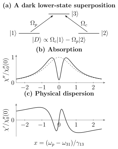
The Λ system and its weak-probe response, for resonant control, and . The lower panels show the physical susceptibility divided by the no-control peak absorption , versus . The solid absorption curve has an interference dip with unsplit poles; the dashed curve is the no-control line. The positive dispersion slope near gives slow-light delay. The lower levels in the scheme are not to a common energy scale.
Optical-depth-limited bandwidth
Section titled “Optical-depth-limited bandwidth”Let be the resonant intensity optical depth without the control. A small residual absorption that looks negligible in a single-atom response can be important after propagation:
for a uniform, dilute sample with and negligible reflections. Its frequency derivative can still be large; weak susceptibility does not mean weak dispersion.
For and a resonant control, expansion near line center gives the angular-frequency half-width at intensity transmission
This value follows from in the narrow-window, large-optical-depth limit. Other width conventions change its numerical factor. The robust scaling is
An input pulse must fit inside this usable window, not merely inside the single-atom EIT width.
EIT Versus Autler–Townes Splitting
Section titled “EIT Versus Autler–Townes Splitting”For resonant control, the displayed denominator has poles
The susceptibility uses the conjugate poles in atom-minus-field detuning; in physical frequency its causal poles lie below the real axis. The real-part separations coincide. These poles acquire distinct real parts only when
EIT suppression instead becomes strong near
When , these conditions are parametrically separated. A narrow central dip can be deep while both poles still share the same real frequency.
The mechanisms are:
- EIT: destructive pathway interference removes absorption inside an otherwise broad response;
- Autler–Townes splitting: a strong control resolves two absorptive dressed resonances.
There is a crossover, not a universal verbal boundary. Near that crossover, the full susceptibility is more informative than decomposing a trace into two unconstrained Lorentzians. Configuration, decay pathways, optical depth, convolution, and noise determine what a spectrum can support.
Autler–Townes Splitting develops the pole, peak, model-selection, and calibration issues in detail.
Dispersion and Slow Light
Section titled “Dispersion and Slow Light”Phase slope
Section titled “Phase slope”The real quadrature of the probe coherence changes rapidly across the transparency window. For ideal resonant EIT with ,
close to line center in the atom-minus-field convention. Consequently and . The minus sign from is essential.
For a dilute medium,
The group index is
and the group velocity is
The transparency window suppresses the absorption that would otherwise accompany a large resonant dispersion.
Delay scaling
Section titled “Delay scaling”For a uniform Λ medium with negligible lower-state decoherence, a resonant control, and the Hamiltonian convention used above, the group delay relative to vacuum scales as
Here the coefficient is fixed by the definitions above: and . Pulse width does not change this infinitesimal phase-slope delay; a broad or reshaped pulse can have a different measured peak delay. The scaling is:
Reducing the control increases delay but narrows the usable bandwidth and increases sensitivity to . Delay, transmission, and distortion must therefore be optimized together.
Combining the ideal delay and propagation-bandwidth estimates gives
This delay–bandwidth scaling shows why optical depth is a resource. It also shows why an arbitrarily weak control does not provide unlimited useful delay.
Pulse conditions
Section titled “Pulse conditions”A delayed pulse should satisfy:
- its spectral support lies within the transparent, approximately linear dispersion region;
- the medium is long enough for measurable delay but not so absorptive that residual loss dominates;
- higher-order dispersion does not strongly reshape the envelope;
- the control remains coherent and sufficiently uniform;
- the pulse duration is long compared with the optical-coherence relaxation time when a steady susceptibility is used.
The compressed pulse length is
where is its duration. For complete storage, the pulse must be substantially contained inside the medium before the control maps it to a matter excitation.
Causality
Section titled “Causality”Group velocity describes the motion of a narrowband envelope under a local linearization of phase. It is not the speed of a discontinuous signal front. EIT slow light is compatible with relativistic causality. Likewise, an anomalous group velocity or pulse advancement in another line-shape regime does not imply superluminal information transfer.
Propagation and Ensemble Effects
Section titled “Propagation and Ensemble Effects”Maxwell–Bloch problem
Section titled “Maxwell–Bloch problem”A measured EIT spectrum is generally not the single-atom coherence plotted against detuning. A slowly varying probe envelope obeys a propagation equation of the schematic form
where contains density, dipole, and field-normalization factors. The coherence at each position depends on the local control, detunings, populations, and velocity class.
The forward model must therefore specify:
- whether the sample is optically thin or thick;
- whether depletion and reshaping are negligible;
- whether the control varies along the medium;
- whether atoms move during the interaction;
- whether the detector measures field, intensity, fluorescence, or phase.
Doppler detunings
Section titled “Doppler detunings”For atom-minus-field detunings and an atom of velocity ,
and
The Λ two-photon detuning is
Co-propagating, nearly equal-wavelength beams minimize this residual. Counter-propagating optical beams create a much larger spin-wave wave vector and faster motional dephasing.
The velocity-averaged susceptibility is
Velocity classes mixed at one position contribute to the local complex susceptibility before propagation. A detector summing separate transverse rays instead averages their transmitted powers after propagation.
Spatially varying control
Section titled “Spatially varying control”If the control has a Gaussian profile, then
Different atoms experience different transparency widths, delays, and light shifts. For optically thin absorbed power or fluorescence, a useful local-signal approximation is
A fit using only the peak control intensity can overestimate the effective window and bias a dipole or field calibration. At substantial optical depth, propagate the field along each ray before summing detected power; the linear volume integral cannot describe all transmission experiments.
Laser coherence
Section titled “Laser coherence”EIT depends on the relative probe–control phase. If both fields are derived coherently from one source, common optical phase noise can cancel while differential phase noise remains. Independent lasers require a relative linewidth and servo-noise model.
In a Markovian approximation, differential phase noise contributes to . Nonstationary drift, colored noise, and scan-to-scan jumps should not be hidden inside one Lorentzian rate when the data resolve them.
Coherent Population Trapping
Section titled “Coherent Population Trapping”EIT and coherent population trapping (CPT) use the same dark-state structure but emphasize different observables.
EIT viewpoint. A weak probe interrogates the linear optical response of a control-prepared medium. Transmission, phase, group delay, and propagation are central.
CPT viewpoint. Repeated coherent excitation and decay pump population into a nonabsorbing superposition. Fluorescence reduction or a dark resonance as the two-photon detuning is scanned is central.
In the weak-probe steady limit, the descriptions overlap. They differ when:
- both fields substantially redistribute populations;
- preparation time is finite;
- branching and repumping determine the steady state;
- the measured channel is fluorescence rather than probe transmission;
- the dark resonance is used as a frequency discriminator.
Connection to STIRAP
Section titled “Connection to STIRAP”The dark state depends on the coupling ratio:
If the ratio changes slowly, a system prepared in can follow that instantaneous eigenstate while avoiding . STIRAP uses a counterintuitive control sequence to rotate the dark state from one bare lower state to the other.
EIT storage instead applies the same adiabatic geometry to a propagating field and a collective spin coherence. The STIRAP page develops the population-transfer protocol and its adiabaticity conditions.
Dark-State Polaritons
Section titled “Dark-State Polaritons”Light–matter normal mode
Section titled “Light–matter normal mode”For a quantized or normalized probe envelope, the transparent propagation mode is a coherent mixture of a photonic field and a collective – spin coherence. In the convention, define a mixing angle by
where is the single-atom probe coupling in the chosen mode normalization and is the number of coherently participating atoms. The weak-excitation approximation requires the number of stored excitations to be small compared with . Define the coarse-grained spin lowering operator with the optical carrier phases removed; its expectation is , not . Use compatible field and collective-spin normalizations throughout.
A representative dark-state polariton is
The exact normalization depends on continuum and density conventions. The mixing content does not:
In the ideal adiabatic limit,
for a spatially uniform control envelope, with
The slow group velocity is therefore the velocity of a hybrid normal mode, not a photon repeatedly stopping between atoms.
Storage and retrieval
Section titled “Storage and retrieval”An idealized EIT memory proceeds as follows:
- establish a transparent window with the control on;
- send a probe pulse whose bandwidth fits inside that window;
- allow the pulse to compress into the medium;
- reduce the control adiabatically, rotating toward ;
- wait for a storage time ;
- restore a control field, converting the spin wave back to light.
During storage, the optical field amplitude is ideally absent and the information resides in a collective matter excitation. For a stored Fock state the mean spin coherence can vanish: the operator mode and its quantum state, rather than a nonzero classical expectation value, carry the information. During adiabatic slowing the pulse bandwidth narrows along with the transparency window; one must not compare the final zero-control window with the unchanged input bandwidth.
Spin-wave phase
Section titled “Spin-wave phase”The stored coherence carries wave vector
For ballistic atoms with a one-dimensional Gaussian velocity projection of RMS width , an ideal spin-wave amplitude can decay as
The corresponding amplitude time is
Trapping, buffer-gas diffusion, wall collisions, magnetic gradients, and many-body interactions require different models.
Adiabaticity
Section titled “Adiabaticity”Changing the mixing angle couples the dark polariton to bright, loss-carrying modes. In a lossless local model, compare the corresponding matrix element (proportional to ) with the bright-mode frequency separation. In a propagating dissipative medium, optical depth, pulse bandwidth, boundaries, and accumulated loss also enter. A complex eigenvalue gap alone is not a sufficient adiabaticity test; check the coupled Maxwell–Bloch evolution when those effects matter.
Turning off the control too rapidly creates bright-state admixture and spontaneous loss. Turning it off too slowly can expose the spin coherence to unnecessary dephasing before mapping is complete.
Quantum-Memory Performance
Section titled “Quantum-Memory Performance”Efficiency
Section titled “Efficiency”For envelopes normalized so is photon flux, the photon-number efficiency is
An energy-efficiency ratio equals this value only for equal input and output carrier frequencies; frequency conversion adds the ratio . For quantum fields, replace the classical squared envelope by the normally ordered flux expectation.
Efficiency depends on optical depth, input temporal mode, control shaping, retrieval direction, decoherence, filtering, and mode matching. At finite optical depth, reabsorption and spontaneous emission prevent unit efficiency even in an otherwise idealized model. Optimized storage is a mode-matching and control problem, not just “turn the control off.”
If the spin-wave amplitude decays exponentially at rate , a simple efficiency model is
The factor of two appears because efficiency is quadratic in amplitude. Gaussian motional dephasing produces a different time dependence.
Fidelity and noise
Section titled “Fidelity and noise”A quantum memory must preserve more than average pulse energy. Relevant metrics include:
- conditional and unconditional state fidelity;
- total efficiency;
- added noise photons per retrieved mode;
- signal-to-noise ratio at the single-photon level;
- storage lifetime;
- temporal, spectral, spatial, and polarization mode overlap;
- phase coherence and process fidelity.
Control leakage, spontaneous Raman scattering, four-wave mixing, detector dark counts, and residual population can create output when no input photon was stored. A bright classical storage trace does not bound that noise tightly enough to establish quantum operation.
Optical depth as a resource
Section titled “Optical depth as a resource”For optimized Λ memories, attainable efficiency is fundamentally governed by optical depth together with decoherence and mode control. Increasing can improve coupling to the desired collective mode, but high density may also increase collisions, radiation trapping, four-wave mixing, and inhomogeneous shifts.
The relevant optical depth is mode and transition specific. An absorption measurement made with different polarization, pumping, temperature, or beam geometry is not automatically the memory optical depth.
Multilevel and Experimental Structure
Section titled “Multilevel and Experimental Structure”Zeeman and hyperfine manifolds
Section titled “Zeeman and hyperfine manifolds”Real atoms supply several Λ pathways:
and
Different Clebsch–Gordan coefficients, light shifts, and two-photon detunings produce overlapping dark resonances. Optical pumping can move population among them during the scan.
Off-resonant light shifts
Section titled “Off-resonant light shifts”The control can shift , , and spectator states. The two-photon resonance then occurs at
where . Only the additional off-resonant corrections are included here; the explicitly modeled control coupling must not be counted a second time as a light shift. Control-power-dependent motion of the dark resonance is not necessarily a calibration error; it can be a physical AC Stark shift.
Dynamic Polarizability and AC Stark Shift derive the corresponding response and shift formulas.
Four-wave mixing
Section titled “Four-wave mixing”Additional Λ pathways can allow the strong control to generate a conjugate field. Four-wave mixing may increase apparent transmission or retrieval while adding noise and changing the mode transformation. A gain-assisted output cannot be interpreted with a passive beam-splitter memory model.
No-input trials, conjugate-mode detection, and state-sensitive noise benchmarks distinguish passive storage from gain-assisted output. Quantum Memories develops the complete write–store–read channel and comparisons with other protocols. Rydberg Electrometry applies ladder transparency to field inference; a steep linear EIT susceptibility alone does not establish a useful photon–photon gate.
Exercises
Section titled “Exercises”1. Which decay destroys a dark state?
Section titled “1. Which decay destroys a dark state?”Write with real . Compare spontaneous-emission jump operators with lower-state dephasing . For an initially pure dark state, find the initial rate of change of its fidelity .
Solution
Every annihilates , as does ; these spontaneous-emission dissipators leave the exactly prepared dark state unchanged. For a Hermitian jump , the initial fidelity rate is . Here
The same dissipator damps at rate . Excited-state decay is harmless to the ideal dark vector; relative lower-state dephasing is not, except at a pure bare-state endpoint.
2. Shift the two-photon resonance
Section titled “2. Shift the two-photon resonance”Add diagonal energy shifts to the three-level Hamiltonian. Find the condition for a vector with zero excited-state amplitude to remain an eigenvector. Does a shift of alone move the dark resonance?
Solution
The two occupied lower components must have equal rotating-frame diagonal energies: . Thus
The optical coupling still cancels for the same amplitude ratio, and the dark eigenvalue is . Changing only changes the bright-state energies and response away from the center, but not this ideal two-photon condition. Additional couplings can change the conclusion.
3. Predict line-center transmission
Section titled “3. Predict line-center transmission”Suppose
and
The resonant no-control intensity optical depth is .
- Find .
- Estimate the line-center transmission with and without the control.
Solution
All rates share the same factor of , so use hertz consistently. The center ratio is
In frequency units,
and
Therefore
The controlled line-center transmission is
Without the control,
The single-atom residual absorption is only about of the original peak, but the optical-depth exponent is still needed to predict the transmitted intensity.
4. Distinguish EIT from split poles
Section titled “4. Distinguish EIT from split poles”Let
and
- Estimate the homogeneous EIT HWHM and FWHM.
- Find the line-center absorption ratio.
- Determine whether the response poles are split.
Solution
The narrow-window estimate is
Thus
and the approximate FWHM is
The line-center ratio is
The pole-splitting threshold is
The applied control is well below that threshold. It produces a deep narrow EIT window without split response poles.
5. Delay and propagation bandwidth
Section titled “5. Delay and propagation bandwidth”Take a resonant Λ medium with:
Neglect .
- Estimate the group delay.
- Estimate the propagation bandwidth in cycles per second.
- Decide whether a pulse with RMS bandwidth is comfortably inside the estimate.
Solution
Using angular quantities,
Substitution gives
For the angular-frequency half-width at intensity transmission,
Dividing by and using the quoted frequency values,
The RMS bandwidth is one third of this transmission half-width. For a Gaussian input intensity spectrum of RMS width , averaging gives
Thus this bandwidth already causes roughly 9.5% filtering loss in the quadratic model. Whether that is acceptable depends on the chosen loss and distortion tolerance; higher-order dispersion must also be checked.
As a consistency check,
6. Change the polariton composition
Section titled “6. Change the polariton composition”Let the collective probe coupling be
Using
find the photonic fraction and for:
- ;
- .
Solution
The photonic fraction is
For ,
so
Hence in this ideal normalized model.
For ,
and
The polariton is then about matter-like by norm, and . Sending adiabatically toward zero completes the ideal mapping to spin coherence.
7. Motional spin-wave dephasing
Section titled “7. Motional spin-wave dephasing”An idealized Λ memory uses co-propagating fields of wavelengths
The one-dimensional velocity RMS is
Using
estimate the spin-wave amplitude time for:
- co-propagating beams;
- counter-propagating beams.
Solution
For co-propagating beams,
Therefore
For counter-propagating beams, the signed wave vectors add:
Thus
The nearly co-propagating geometry lengthens this ballistic motional time by about two orders of magnitude. Other dephasing mechanisms may then become the limit.
8. Diagnose a transparency experiment
Section titled “8. Diagnose a transparency experiment”A broad probe line has HWHM . With a control corresponding to , a -wide central transmission window appears. The window follows the probe–control frequency difference, disappears when relative phase noise is added, and becomes shallower as lower-state decoherence is increased. No two maxima are resolved.
- Which observations support an EIT interpretation?
- Why is a resolved Autler–Townes interpretation unsupported?
- What additional measurements would strengthen the claim?
Solution
The narrow feature follows two-photon rather than one-photon detuning. Its sensitivity to relative phase noise and lower-state decoherence directly implicates the coherence . A narrow dip embedded inside a much broader optical line is also consistent with the hierarchy .
The control strength is below the approximate split-pole scale:
No two maxima are resolved, so the data do not support a claim that the transparency is merely the valley between a resolved Autler–Townes pair.
Useful additional checks include:
- fit the complex three-level susceptibility with independently constrained and ;
- measure both transmission and probe phase;
- vary and test the predicted depth and width scalings;
- repeat at lower probe power;
- reverse or vary beam geometry to test two-photon Doppler behavior;
- measure laser relative phase noise and the instrument response;
- compare against optical-pumping and spectral-hole alternatives.
These measurements can support EIT without pretending that every intermediate-strength spectrum has a unique verbal decomposition.
References
Section titled “References”- T. Y. Abi-Salloum, “Electromagnetically induced transparency and Autler–Townes splitting: Two similar but distinct phenomena in two categories of three-level atomic systems,” Physical Review A 81, 053836 (2010).
- K.-J. Boller, A. Imamoglu, and S. E. Harris, “Observation of electromagnetically induced transparency,” Physical Review Letters 66, 2593–2596 (1991).
- M. Fleischhauer, A. Imamoglu, and J. P. Marangos, “Electromagnetically induced transparency: Optics in coherent media,” Reviews of Modern Physics 77, 633–673 (2005).
- M. Fleischhauer and M. D. Lukin, “Dark-state polaritons in electromagnetically induced transparency,” Physical Review Letters 84, 5094–5097 (2000).
- M. Fleischhauer and M. D. Lukin, “Quantum memory for photons: Dark-state polaritons,” Physical Review A 65, 022314 (2002).
- A. V. Gorshkov, A. André, M. D. Lukin, and A. S. Sørensen, “Photon storage in Λ-type optically dense atomic media. II. Free-space model,” Physical Review A 76, 033805 (2007).
- S. E. Harris, “Normal modes for electromagnetically induced transparency,” Physical Review Letters 72, 52–55 (1994).
- L. V. Hau, S. E. Harris, Z. Dutton, and C. H. Behroozi, “Light speed reduction to 17 metres per second in an ultracold atomic gas,” Nature 397, 594–598 (1999).
- C. Liu, Z. Dutton, C. H. Behroozi, and L. V. Hau, “Observation of coherent optical information storage in an atomic medium using halted light pulses,” Nature 409, 490–493 (2001).
- D. F. Phillips, A. Fleischhauer, A. Mair, R. L. Walsworth, and M. D. Lukin, “Storage of light in atomic vapor,” Physical Review Letters 86, 783–786 (2001).