

Multipole Expansion
The multipole expansion organizes how a localized charge and current distribution exchanges energy, momentum, and angular momentum with an electromagnetic field. Electric-dipole coupling, E1, is only its leading term. Magnetic-dipole M1, electric-quadrupole E2, and higher multipoles become essential when E1 is forbidden, accidentally small, suppressed by mode geometry, or inadequate at the target precision.
For a localized neutral system at rest, in a prescribed smooth classical field with near the charges, the first local interactions are
Here is the magnetic dipole and is the traceless electric quadrupole in the convention defined below. The three terms sample different local features of the same mode: electric field, magnetic field, and electric-field gradient.
The expansion is useful only when two ideas are kept separate:
- Multipole order classifies interaction amplitudes by spatial structure and radiation symmetry.
- Perturbative order counts powers of the interaction in a transition process.
An E2 transition is first order in a weak applied field but subleading in the spatial multipole expansion. A two-photon E1–E1 transition is second order in the field interaction but uses E1 operators at each vertex.
Required background. Dipole Approximation separates internal and motional length scales; Multipole Operators provides tensor rank and parity; Atomic Selection Rules applies them to fine and hyperfine levels.
From Spatial Coupling to Multipoles
Section titled “From Spatial Coupling to Multipoles”Plane-wave expansion
Section titled “Plane-wave expansion”For an internal coordinate and a plane-wave component,
The internal factor expands as
Charge and current conservation reorganize these powers into electric and magnetic multipoles. A consistent first correction to E1 contains both M1 and E2. Keeping one arbitrarily selected Cartesian Taylor term is not generally equivalent to keeping a complete multipole order.
The center-of-mass phase
is not part of the internal multipole truncation. It can still produce recoil, Doppler shifts, and motional sidebands.
Spherical-wave viewpoint
Section titled “Spherical-wave viewpoint”An exact radiation field about an origin can also be decomposed into electric and magnetic spherical multipoles. Their radial dependence contains spherical Bessel functions. At small argument,
This small- behavior generates the long-wavelength hierarchy. For typical nonzero electric moments,
Magnetic moments contain internal currents. A common nonrelativistic estimate is
when both comparison amplitudes are allowed and have otherwise comparable structure. Neither estimate is a selection rule. A zero E1 denominator means a higher multipole must be compared with the leading nonzero amplitude instead.
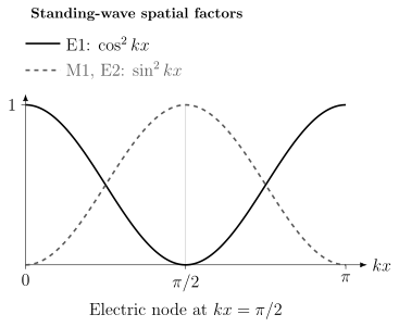
Squared spatial coupling factors for the standing wave derived below, each normalized to its own maximum. At , the E1 field factor vanishes and the M1/E2 factors are maximal. Their real temporal factors differ, and the atomic matrix elements still set the relative absolute strengths.
Gauge, origin, and truncation
Section titled “Gauge, origin, and truncation”The exact minimal-coupling and multipolar theories are unitarily related when states, observables, self-energy terms, and boundary conditions are transformed together. Their truncated pieces need not agree term by term.
An origin shift also mixes Cartesian multipole coefficients. Observable amplitudes remain origin independent when all contributions through the claimed order are retained. Beyond E1, this includes interference terms in the probability, not only squares of selected M1 or E2 amplitudes.
These issues are developed in Gauge Choices in Light–Matter Physics and Dipole Approximation.
Electric Dipole E1
Section titled “Electric Dipole E1”Coupling and matrix element
Section titled “Coupling and matrix element”The leading electric interaction is
For a transition ,
E1 samples the electric field itself. In a freely propagating optical mode, it usually dominates allowed transitions because it carries no additional internal factor of or .
Spontaneous rate
Section titled “Spontaneous rate”For a vacuum transition with angular frequency , the polarization- and direction-summed E1 rate can be written
Use the Wigner–Eckart convention
Then the line strength is
The factor results from the angular sums. In isotropic vacuum, summing over all final , directions, and polarizations gives the same total rate for every initial of a degenerate multiplet; averaging is unnecessary for that total. Resolved emission or an anisotropic photonic environment requires the individual angular channels.
The factor contains both the field amplitude per photon and the three-dimensional photon density of states. A matrix element alone does not set a lifetime.
Magnetic Dipole M1
Section titled “Magnetic Dipole M1”Magnetic moment operator
Section titled “Magnetic moment operator”The M1 interaction is
For nonrelativistic particles with orbital and spin angular momenta, a schematic magnetic moment is
For an electron,
Relativistic, anomalous-moment, nuclear, and many-electron corrections are added according to the required accuracy.
Unlike , the magnetic dipole is an axial vector. M1 therefore has rank but even parity. This makes it a common channel between same-parity fine-structure or hyperfine levels.
Field scale and E1 comparison
Section titled “Field scale and E1 comparison”For a plane wave in vacuum,
The same-field amplitude comparison is therefore
Using characteristic electronic moments
gives
The corresponding rate suppression is roughly
at the same frequency and for comparable angular factors. Real matrix elements can differ by orders of magnitude.
Spontaneous rate
Section titled “Spontaneous rate”With the analogous reduced magnetic line strength
the free-space rate is
M1 and E1 share the phase-space scaling. The enormous lifetime of a low-frequency M1 line can therefore come from frequency as well as from its magnetic matrix element.
The hydrogen ground-state hyperfine transition near is a canonical example. It is M1 allowed, but its gigahertz frequency makes its vacuum spontaneous rate extremely small compared with an optical transition of similar dimensionless angular strength.
Mode geometry
Section titled “Mode geometry”M1 responds to , not to the electric field. In a traveling plane wave, the two are locked by Maxwell’s equations. In a standing wave, cavity, waveguide, or near field, their local nodes and antinodes can differ. Placing a system near an electric node can suppress E1 while retaining M1.
The magnetic field also chooses spherical components relative to the quantization axis. A statement such as “M1 is allowed” is incomplete until the field orientation and addressed magnetic sublevels are specified.
Electric Quadrupole E2
Section titled “Electric Quadrupole E2”Quadrupole conventions
Section titled “Quadrupole conventions”Define the primitive second moment
Its interaction with a smooth electric field is
A common traceless quadrupole is
In a source-free region,
so the same interaction becomes
The coefficients and refer to different tensor definitions. Quoting an E2 matrix element without its convention is insufficient.
Gradient coupling
Section titled “Gradient coupling”For a plane wave,
The E2 transition amplitude is therefore
With
one obtains the usual scale estimate
when the E1 denominator is nonzero. The E2 rate is then typically suppressed by relative to a comparable E1 line at the same frequency.
E2 samples the symmetric rank- part of the electric-field gradient. A large scalar gradient estimate does not guarantee coupling to a chosen tensor component; atomic orientation, polarization, propagation direction, and magnetic sublevels all matter.
Same parity and rank two
Section titled “Same parity and rank two”E2 is parity even and has rotational rank . It can therefore connect same-parity levels with angular separations inaccessible to E1 or M1. The transition in near is a standard E2 example.
The complete rank- triangle and projection rules are derived in Multipole Operators and their atomic application in Atomic Selection Rules.
Standing-wave and near-field enhancement
Section titled “Standing-wave and near-field enhancement”At a standing-wave electric node,
while
The local E1 drive then vanishes while E2 can remain finite. This does not make the intrinsic E2 matrix element larger. It changes the field factor multiplying each operator.
Nanophotonic and near-field structures can provide gradients on scales shorter than the free-space wavelength. The relevant expansion parameter is then , and the full mode profile must satisfy Maxwell boundary conditions. A gradient enhancement should be compared with loss, surface noise, modified spontaneous emission, and breakdown of a low-order expansion.
Transition quadrupole versus static quadrupole
Section titled “Transition quadrupole versus static quadrupole”The off-diagonal quantity
drives an E2 transition. The diagonal quantity
is a static quadrupole moment and can shift a level in a static electric gradient.
These are different matrix elements. An E2 clock transition does not by itself prove that the clock shift has a nonzero static quadrupole moment, and a state with a static quadrupole can participate in a transition of another multipolarity. Clock systematics must be evaluated state by state.
Higher Multipoles
Section titled “Higher Multipoles”Electric moments
Section titled “Electric moments”A spherical electric multipole operator can be defined as
where
It has rank and parity . E3 is the electric octupole, E4 the electric hexadecapole, and so on.
For comparable electric structure,
The corresponding rate hierarchy is nominally
before matrix-element, frequency, and angular factors are included.
Magnetic moments
Section titled “Magnetic moments”Magnetic multipoles are current and magnetization moments. M2 has rank and odd parity; M3 has rank and even parity. Their exact operators are more model dependent than the charge-only electric moments because convection current, spin magnetization, relativistic corrections, and many-body currents can all contribute.
The robust labels are
Electric octupole clock line
Section titled “Electric octupole clock line”The transition
near is E3. Its suppression produces an exceptionally long radiative lifetime. Lange and colleagues inferred the matrix element from the resonant Rabi frequency, probe Stark shift, and differential polarizability. Their 2026 erratum corrects the resulting lifetime to
about years. The correction distinguishes peak field squared from the cycle average ; it was not obtained by watching a single ion decay for years. The same weakness that yields a tiny natural linewidth requires substantial probe intensity or long coherent interrogation and creates sensitivity to probe-induced Stark shifts.
Electric monopole is not a one-photon line
Section titled “Electric monopole is not a one-photon line”E0 has rank and even parity, but a real transverse photon cannot carry zero total angular momentum about the emission origin. Charge conservation also prevents a time-dependent total monopole charge in an isolated atomic transition.
Nuclear E0 transitions in internal conversion or pair creation probe radial charge redistribution (for example a charge-radius matrix element), not a changing total charge. Scalar operators can also contribute in collisions or other probes. It does not describe ordinary single-real-photon atomic emission.
Higher multipole versus multiphoton
Section titled “Higher multipole versus multiphoton”An E3 transition is one-photon coupling through a rank- operator. A two-photon E1–E1 process contains two rank- vertices and intermediate state denominators. They can obey different angular, parity, intensity, and frequency rules.
For example, hydrogen decays mainly by two-photon E1–E1 emission, not by relabeling the transition as a high one-photon multipole.
When to keep the full spatial operator
Section titled “When to keep the full spatial operator”If
many multipoles can contribute and the hierarchy can converge slowly. Retaining the exact dependence or the full current–field interaction is often safer than extending a truncated series to high order.
This is particularly relevant in X-ray spectroscopy, large molecules, Rydberg and continuum processes, and strongly structured near fields.
Selection-Rule Summary
Section titled “Selection-Rule Summary”For an irreducible multipole of rank , the exact angular condition is
Its spherical component fixes
If the states have definite parity,
The most common one-photon cases are:
| Type | Rank | Parity relation | Field sampled |
|---|---|---|---|
| E1 | opposite | ||
| M1 | same | ||
| E2 | same | rank- part of | |
| M2 | opposite | magnetic gradient | |
| E3 | opposite | second electric gradient |
These are necessary conditions, not strength predictions. A reduced matrix element can vanish because of configuration, spin, radial orthogonality, exchange symmetry, or cancellation.
Mixed M1 and E2 lines
Section titled “Mixed M1 and E2 lines”M1 and E2 have the same parity and can both contribute when the angular triangle permits them. The amplitude for a resolved propagation direction and polarization is then
Interference depends on geometry, state preparation, and what is integrated over. A database label such as M1+E2 means that one line strength without a specified decomposition is not sufficient.
State mixing
Section titled “State mixing”State mixing can relax an approximate selection rule, but it cannot break an exact symmetry that the mixing Hamiltonian preserves. Electrostatic configuration interaction, spin–orbit coupling, ordinary hyperfine coupling, and a uniform magnetic field preserve parity: they cannot create E1 coupling between exact same-parity states. They can relax approximate spin or electronic-J restrictions on an opposite-parity transition. A static electric field can mix opposite parity and open E1 coupling between levels that had the same field-free parity. A small allowed admixture can dominate a weak bare higher-multipole channel.
The correct procedure is to diagonalize the stated Hamiltonian, evaluate all relevant operators between the dressed states, and compare amplitudes. Field-free labels remain useful descriptors, not exact rules, after strong mixing.
From Amplitudes to Rates
Section titled “From Amplitudes to Rates”Frequency scaling
Section titled “Frequency scaling”With a standard reduced line strength ,
where or . The constant contains SI factors and depends on the normalization chosen for the multipole operator.
The robust frequency powers are:
| Multipole | Frequency factor in the free-space rate |
|---|---|
| E1 or M1 | |
| E2 or M2 | |
| E3 or M3 |
This is why low-frequency fine-structure and hyperfine M1 lines can have very long lifetimes even when their dimensionless angular matrix elements are ordinary.
Lifetime and branching
Section titled “Lifetime and branching”For an isolated upper state in isotropic vacuum, its one-photon width is
Different radiation multipoles are orthogonal after the complete vacuum mode sum, so their total rates add. Add multiphoton emission separately, . For independent, stationary loss channels with negligible return,
The branching fraction for one channel is
“E2 lifetime” is meaningful only if E2 is known to dominate the complete width. A coherent drive or population recycling generally requires coupled equations rather than an extra constant loss rate; modifications of a radiative channel must not also be counted as a separate loss.
Stimulated driving is not set by A alone
Section titled “Stimulated driving is not set by A alone”A spontaneous rate characterizes coupling to the available vacuum modes. For peak complex fields defined by and a rotating-wave off-diagonal element , the couplings are:
A cavity or nanophotonic structure can enhance selected field factors and modify the photonic density of states. The free-space lifetime is then not the whole dynamical model.
Database conventions
Section titled “Database conventions”Atomic transition databases may tabulate , oscillator strength, and line strength using different units and upper-level degeneracy factors. NIST, for example, uses distinct conversion constants for E1, M1, E2, M2, E3, and M3 and explicitly labels mixed M1+E2 lines.
Before converting a tabulated number:
- identify whether the quoted wavelength is vacuum or air;
- identify the upper and lower level convention;
- check whether , , , or is tabulated;
- check the units and multipole normalization;
- use the uncertainty or accuracy grade rather than inventing precision.
Forbidden Transitions and Precision Clocks
Section titled “Forbidden Transitions and Precision Clocks”Forbidden means operator specific
Section titled “Forbidden means operator specific”A line is never simply “forbidden.” It is forbidden for a named operator under stated symmetries. A same-parity line can be E1 forbidden and E2 allowed. A line can be forbidden for every positive-rank one-photon multipole when is the full conserved angular momentum. Electronic can acquire E1 strength through hyperfine mixing because ceases to be exact; the full atomic one-photon restriction still holds. A two-photon process is a different possibility.
The total observed line can contain:
- a bare M1, E2, or higher one-photon amplitude;
- an E1 amplitude borrowed through state mixing;
- a multiphoton amplitude;
- collision- or environment-induced coupling;
- several coherent amplitudes that interfere.
Narrowness and quality factor
Section titled “Narrowness and quality factor”For an upper state with population lifetime , a stable lower state, and no additional coherence decay, the weak-probe Lorentzian full width is
The natural quality factor is
Suppressing fast E1 decay can therefore produce enormous . In an actual clock, the observed linewidth may instead be limited by probe coherence, finite interrogation time, collisions, magnetic noise, or motion.
Representative mechanisms
Section titled “Representative mechanisms”- Hydrogen : an M1 hyperfine transition with strong suppression of spontaneous emission.
- and ion clocks: same-parity E2 transitions.
- : an E2 clock transition near and an E3 clock transition near in the same ion.
- Fermionic alkaline-earth-like clocks: nominal lines are enabled by hyperfine mixing; they should not be described as simply M1 or E2.
- Bosonic clocks: controlled field-induced mixing or multiphoton schemes may open an otherwise forbidden line.
The long lifetime permits longer phase accumulation, provided the laser, motion, and other decoherence sources remain sufficiently quiet. It does not increase phase sensitivity at a fixed interrogation time. Weak coupling can require a longer pulse or higher intensity, increasing the importance of probe Stark shifts and off-resonant excitation.
Quadrupole shifts
Section titled “Quadrupole shifts”An excited state with a nonzero static electric quadrupole moment couples to trap or environmental electric-field gradients. This can shift and inhomogeneously broaden an ion-clock transition:
Orientation averaging, averaging over Zeeman components, field-axis rotation, dynamical decoupling, or choosing states with vanishing tensor moments can suppress the shift. The required strategy depends on the actual state and apparatus.
Precision Spectroscopy develops frequency inference, clock comparison, and systematic shifts.
Worked Examples
Section titled “Worked Examples”E2 suppression for a visible atomic transition
Section titled “E2 suppression for a visible atomic transition”Take
Then
For comparable nonzero internal moments and angular factors,
and
If E1 is exactly zero, the second ratio is not a branching estimate. E2 can be the leading available channel despite its absolute smallness.
Frequency suppression of a magnetic-dipole line
Section titled “Frequency suppression of a magnetic-dipole line”Compare two hypothetical M1 lines with the same reduced matrix element, one at
and one at
Since ,
This comparison isolates phase space. Actual hyperfine and optical magnetic matrix elements need not be equal.
Standing-wave node
Section titled “Standing-wave node”A Maxwell-consistent standing wave can be written
At
the electric field vanishes while
are maximal in space. E1 is locally suppressed, while M1 and E2 have nonzero field factors. Their temporal phases differ by a quarter cycle, so coherent interference also depends on timing and complex-amplitude conventions.
Natural quality factor
Section titled “Natural quality factor”For
the optical frequency is
The lifetime-limited linewidth and quality factor are
This is a natural limit, not a guarantee that a laboratory interrogation will resolve a line.
Exercises
Section titled “Exercises”1. Derive the standing-wave fields
Section titled “1. Derive the standing-wave fields”Two equal plane waves propagate along with electric polarization . Show that their sum can be written
up to an overall phase convention. Identify where E1, M1, and E2 field factors are maximal.
Solution
Choose traveling fields
Using
their electric fields sum to
For the wave,
For the wave,
Their sum is
E1 samples and is maximal at . M1 samples and is maximal at
Since
the E2 field gradient is also spatially maximal at the electric nodes. M1 and E2 differ in temporal phase for the real-field convention used here.
2. Average a static quadrupole shift
Section titled “2. Average a static quadrupole shift”For a traceless level quadrupole , suppose three measurements rotate a fixed, axially symmetric field gradient through orthogonal directions . Write its tensor as and show that the average first-order quadrupole shift vanishes. What must remain fixed?
Solution
The energy shift is . The three directions obey , hence
The shifts therefore average to zero with equal weights. This requires the same gradient magnitude and the same state quadrupole relative to the chosen reference frame in all three measurements; experimentally one may instead rotate the quantization axis relative to a fixed gradient. Drift, unequal weighting, misalignment, or mixing beyond first-order perturbation theory leaves a residual. Scalar shifts do not cancel by this tensor argument.
3. E2 and E3 power counting
Section titled “3. E2 and E3 power counting”For , estimate the E2 and E3 amplitudes and rates relative to E1 when all intrinsic coefficients are comparable and nonzero.
Solution
The electric amplitude hierarchy gives
and
Squaring gives the nominal rate ratios
The result assumes the same frequency and no symmetry zero. A real E3 clock line can still dominate when all lower multipoles vanish.
4. Use the full rank condition
Section titled “4. Use the full rank condition”Without rederiving the Wigner–Eckart theorem, apply
to classify pairs
for M1 and E2. Ignore parity until the final sentence.
Solution
M1 has .
- fails because is false.
- satisfies .
- fails because .
- fails because the angular separation is .
E2 has .
- fails because is false.
- fails because is false.
- satisfies .
- satisfies .
Both M1 and E2 have even parity, so any angularly allowed pair must also have the same initial and final parity.
5. Competing widths and branching
Section titled “5. Competing widths and branching”An excited level has radiative rates
Blackbody transfer adds and collisions add . Find the lifetime and unconditional probabilities for each spontaneous radiative decay channel, assuming stationary independent rates and no repopulation.
Solution
The total width is
Therefore
For these unconditional decay probabilities, the denominator is the total width. Branching fractions conditioned on spontaneous radiative emission alone would instead divide by :
The radiative branches sum to because blackbody and collisional channels consume the remaining probability.
6. Natural linewidth of an E3 clock state
Section titled “6. Natural linewidth of an E3 clock state”Use the measured lifetime
and frequency
to estimate the lifetime-limited linewidth and quality factor.
Solution
The natural linewidth is
The natural quality factor is
This natural does not mean a laboratory laser can interrogate for years. Probe coherence, technical noise, state loss, and practical cycle time set much shorter operational times.
7. Distinguish transition and static quadrupoles
Section titled “7. Distinguish transition and static quadrupoles”An ion has
Which quantities control coherent E2 excitation and the differential static quadrupole shift?
Solution
Coherent E2 excitation depends on the off-diagonal transition moment:
The static shift of each level depends on its diagonal moment:
The clock shift is the difference,
With the stated values, the ground-state static quadrupole contribution vanishes but the excited-state contribution does not. The transition can be E2 driven and quadrupole shifted, but the two effects involve different matrix elements and potentially different fields.
8. E0 or two photon?
Section titled “8. E0 or two photon?”Two atomic states both have and the same parity. Explain why the rank- label E0 does not make ordinary one-photon emission possible, and why a two-photon E1–E1 process may still occur.
Solution
A real transverse photon carries at least one unit of total angular momentum in a multipole expansion about the emitter. An isolated atomic transition also cannot radiate a changing net charge monopole. Therefore E0 is not an ordinary single-real-photon emission channel.
A two-photon process is different. Two rank- E1 interactions act in second-order perturbation theory through intermediate states. Their coupled angular momenta can include total rank , and the product of two odd-parity E1 operators is even. Thus same-parity transitions can be allowed through E1–E1 two-photon emission when energy, intermediate-state sums, and other symmetries permit it.
References
Section titled “References”- D. L. Andrews, G. A. Jones, A. Salam, and R. G. Woolley, “Perspective: Quantum Hamiltonians for optical interactions,” Journal of Chemical Physics 148, 040901 (2018), doi:10.1063/1.5018399.
- M. Babiker and R. Loudon, “Derivation of the Power–Zienau–Woolley Hamiltonian in quantum electrodynamics by gauge transformation,” Proceedings of the Royal Society A 385, 439–460 (1983), doi:10.1098/rspa.1983.0022.
- C. Cohen-Tannoudji, J. Dupont-Roc, and G. Grynberg, Photons and Atoms: Introduction to Quantum Electrodynamics, Wiley, 1989.
- C. Cohen-Tannoudji, J. Dupont-Roc, and G. Grynberg, Atom–Photon Interactions: Basic Processes and Applications, Wiley, 1992.
- D. P. Craig and T. Thirunamachandran, Molecular Quantum Electrodynamics, Dover, 1998.
- P. Dubé, A. A. Madej, J. E. Bernard, L. Marmet, J.-S. Boulanger, and S. Cundy, “Electric Quadrupole Shift Cancellation in Single-Ion Optical Frequency Standards,” Physical Review Letters 95, 033001 (2005), doi:10.1103/PhysRevLett.95.033001.
- R. M. Godun, P. B. R. Nisbet-Jones, J. M. Jones, S. A. King, L. A. M. Johnson, H. S. Margolis, K. Szymaniec, S. N. Lea, K. Bongs, and P. Gill, “Frequency Ratio of Two Optical Clock Transitions in and Constraints on the Time Variation of Fundamental Constants,” Physical Review Letters 113, 210801 (2014), doi:10.1103/PhysRevLett.113.210801.
- J. F. Goodwin, G. Stutter, R. C. Thompson, and D. M. Segal, “Resolved-Sideband Laser Cooling in a Penning Trap,” Physical Review Letters 116, 143002 (2016), doi:10.1103/PhysRevLett.116.143002.
- A. Kramida, Yu. Ralchenko, J. Reader, and the NIST ASD Team, NIST Atomic Spectra Database, version 5.12, National Institute of Standards and Technology, 2024, doi:10.18434/T4W30F, accessed 2026-10-14.
- R. Lange, A. A. Peshkov, N. Huntemann, Chr. Tamm, A. Surzhykov, and E. Peik, “Lifetime of the Level in for Spontaneous Emission of Electric Octupole Radiation,” Physical Review Letters 127, 213001 (2021), doi:10.1103/PhysRevLett.127.213001; erratum, Physical Review Letters 136, 249901 (2026), doi:10.1103/6zt4-vgwj.
- A. D. Ludlow, M. M. Boyd, J. Ye, E. Peik, and P. O. Schmidt, “Optical Atomic Clocks,” Reviews of Modern Physics 87, 637–701 (2015), doi:10.1103/RevModPhys.87.637.
- W. C. Martin and W. L. Wiese, “Atomic Spectroscopy: An Introduction,” in G. W. F. Drake, ed., Atomic, Molecular, and Optical Physics Handbook, AIP Press, 1996.
- E. A. Power and S. Zienau, “Coulomb gauge in non-relativistic quantum electro-dynamics and the shape of spectral lines,” Philosophical Transactions of the Royal Society A 251, 427–454 (1959), doi:10.1098/rsta.1959.0008.
- I. I. Sobelman, Atomic Spectra and Radiative Transitions, 2nd ed., Springer, 1992.