

Quantum Estimation for Magnetometry
A magnetometer estimates a specified property of a magnetic field from a physical response. In quantum magnetometry, that response is encoded in a quantum state or quantum dynamical process before a measurement produces classical data. The phrase “magnetic-field sensitivity” is incomplete until the field component, spatial weighting, temporal waveform, bandwidth, averaging convention, dynamic range, and operating conditions are stated.
Required background. Parameter estimation, Fisher information, and Ramsey interferometry supply the likelihood and readout. Spin in magnetic fields defines the signed magnetic coupling.
For optical pumping, SERF operation, coil calibration, and instrument systematics, see AMO Magnetometry.
Magnetic-field components and modes
Section titled “Magnetic-field components and modes”A magnetic field is a vector field over space and time. A useful experiment rarely estimates all of it. Instead, it estimates one or several parameters in a model such as
Here is the target parameter, is its known spatiotemporal mode, and the are nuisance parameters. Depending on the task, might be
- a static field component at a calibrated location;
- the amplitude and phase of a sinusoidal field;
- a gradient or difference between two regions;
- a Fourier coefficient in a prescribed bandwidth;
- a source parameter inferred through a field model; or
- a stochastic quantity such as a power spectral density.
These are different statistical problems. A protocol optimized for a known sinusoid can reject a static offset and yet be a poor broadband magnetometer. A gradiometer can reject uniform environmental noise while being deliberately insensitive to the common field. A relaxometry experiment estimates noise near a transition frequency rather than a deterministic field amplitude.
A sensitivity must therefore be attached to a field model and an observation model, rather than only to the name of the instrument.
Magnetic Coupling as a Parameter Generator
Section titled “Magnetic Coupling as a Parameter Generator”Let a controlled sensor couple to an effective field component through
where is the signed gyromagnetic ratio and is a dimensionless generator. For a spin- sensor with quantization axis , . For spins responding collectively,
Suppose control pulses produce a toggling function and the target field is . If the effective generators commute at different times, the parameter-dependent unitary is
The overlap is the temporal signal gain. For a static field and free precession, and . A spin echo has equal positive and negative lobes, so it rejects a static field but can acquire phase from an alternating field synchronized to the sign changes.
For a pure input state, the quantum Fisher information (QFI) for is
This equation separates three ingredients:
- the coupling strength ;
- the temporal overlap ; and
- the generator variance supplied by the probe state.
It is a local information measure for the specified parameter model. It does not by itself state the capture range, identify a realizable measurement, include cycle overhead, or guarantee robustness to nuisance fields.
A Binary Magnetometry Likelihood
Section titled “A Binary Magnetometry Likelihood”Ramsey-like preparation and readout often produce a binary outcome with likelihood
The analysis phase selects the working point. With the signed Hamiltonian above, one compatible qubit measurement is on an initially -polarized state. This fixes the sign of the displayed sine fringe.
The effective contrast can describe independent dephasing and symmetric readout errors. Asymmetric classification requires an offset as well. Here is treated as known and independent of . The classical Fisher information is
At quadrature, where the sine term vanishes,
For independent, identically coupled spins read out in one cycle, the information adds. A shared random field must first be included in their joint likelihood; averaging it into the single-spin contrast does not preserve independence:
The same scaling follows from the QFI. An equatorial coherent spin state has , giving
before contrast loss. Equality between a measurement’s classical Fisher information and the QFI requires the appropriate state, working point, and readout; quoting QFI alone does not establish experimental sensitivity.
Sensitivity Means Information per Wall Time
Section titled “Sensitivity Means Information per Wall Time”Let the complete cycle last
For statistically independent cycles at a fixed working point, the Fisher information rate is
The corresponding local Cramér–Rao sensitivity coefficient is
For free-precession DC sensing, . Under the assumptions above, an averaging time gives
The units of are . It was defined here by . For a continuous white-noise record with unit DC response, a rectangular average has when is a one-sided PSD per hertz. Thus the corresponding one-sided amplitude spectral density is , rather than . The averaging filter and spectral convention fix this conversion.
Dead time matters twice. It reduces the number of trials per unit time, and it can expose a pulsed sensor to aliasing of environmental or local-oscillator noise. Rejected cycles, preparation failures, recalibration, and recovery from saturation belong in or in a separately reported duty factor.
Worked benchmark
Section titled “Worked benchmark”Consider independent spins with
For a static field, , so the ideal projection-noise benchmark is
This is not yet an instrument specification. It omits technical readout noise, field calibration, spatial averaging, correlated cycles, estimator loss, dynamic range, and uptime. Its value is that it states a transparent reference against which the complete device can be compared.
Temporal Modes and Filter Matching
Section titled “Temporal Modes and Filter Matching”Write the field along the sensed axis as
where is a deterministic target waveform and is stationary zero-mean magnetic noise. The accumulated phase is
The control modulation is therefore both a signal template and a noise filter. Define
For a sinusoidal signal ,
With the two-sided power spectral density convention
the phase variance is
For Gaussian phase noise, the coherence is
Different spectral conventions move factors of two between , , and the integration range. The physical prediction is unchanged if one convention is used consistently.
For one ideal echo pulse at , in the first half and in the second. Comparing its Fourier transform with free Ramsey precession gives
The zero-frequency limits are and zero. For the known signal , Ramsey gives and echo gives .
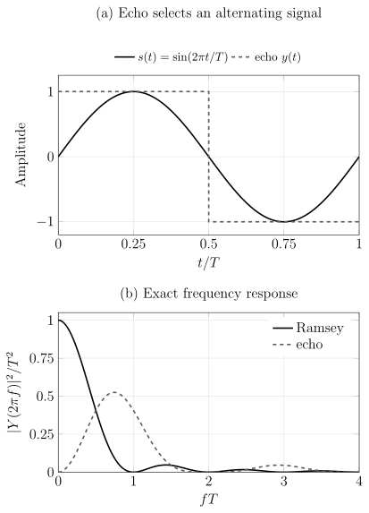
(a) One echo pulse reverses the sign of the interaction, making both halves of the sinusoidal signal add to the accumulated phase. (b) The exact normalized filters show the cost: echo rejects a constant field while retaining nonzero-frequency response. The waveform phase matters as well as the filter magnitude; a shifted sinusoid can have a different overlap.
Filter matching has a hard limitation: control cannot reject noise that is indistinguishable from the signal in the same spatiotemporal mode. More pulses can suppress low-frequency noise while sharpening an AC passband, but pulse errors, finite pulse duration, timing jitter, harmonics, and reduced duty factor can erase the expected gain. The ideal and the measured transfer function should both be reported.
Coherence and the Optimal Interrogation Time
Section titled “Coherence and the Optimal Interrogation Time”Longer interrogation increases phase gain, but it usually reduces contrast. For a phenomenological stretched-exponential envelope with ,
where refers to the actual DC interrogation (often denoted for free precession, not the longer echo coherence time), the information rate with negligible overhead is
Its optimum satisfies
With fixed dead time , the rate becomes
and the stationary condition is
This optimization is local and model-dependent. Phase wrapping may force a shorter ; overhead can favor a longer ; colored noise can invalidate the stretched-exponential model; and adaptive multi-time protocols can combine a wide capture range with a long final interrogation.
Bandwidth, Dynamic Range, and Aliasing
Section titled “Bandwidth, Dynamic Range, and Aliasing”A single sensitivity number hides the sensor transfer function. At minimum, one should distinguish
- interrogation bandwidth: the width of the temporal filter around its target frequency;
- sampling bandwidth: limited by cycle time and irregular dead time;
- closed-loop bandwidth: relevant when feedback tracks a field;
- analysis bandwidth: imposed by the estimator or reported spectrum; and
- usable bandwidth: the region over which calibration, linearity, and noise are validated.
The binary likelihood is periodic in phase. For one interrogation, fields separated by
produce the same ideal probability. A roughly linear single-fringe interval is smaller still. Increasing improves local sensitivity while reducing unambiguous range. Bias fields, quadrature readout, multiple interrogation times, adaptive control, and an independent coarse channel can resolve aliases, but those resources belong in the protocol description.
For a continuously operated linear sensor, it is often clearer to write
where is the measured output and is the calibrated complex response. Output noise referred to the input gives
An amplitude spectral density has units ; the PSD has units ; and a one-shot standard deviation has units . These quantities should not be interchanged.
Spatial Modes and Source Geometry
Section titled “Spatial Modes and Source Geometry”Real sensors average the field over a finite region. A scalar channel can be modeled as
The kernel includes sensor density, optical intensity, mode overlap, collection efficiency, and analysis weighting. The local sensitive axis is . Two devices with the same field-noise floor can have very different value for a localized source because their active volumes, standoff distances, and kernels differ.
Spatial resolution is not simply the physical sensor size. It also depends on source distance, field propagation, channel geometry, inversion priors, and regularization. For a multi-channel array,
where denotes a source distribution and is a forward kernel. Estimating the source is then an inverse problem, not merely a collection of independent field estimates. Cross-channel covariance and uncertainty in the kernels must enter the inference.
A gradiometer estimates a difference such as
Common-mode rejection depends on matched gains, axes, transfer functions, and timing. A low differential noise floor does not establish the absolute noise of either channel.
Vector Magnetometry Is Multiparameter Estimation
Section titled “Vector Magnetometry Is Multiparameter Estimation”For a spin coupled to all three components,
At zero field, the pure-state QFI matrix is
where . This expression also gives the leading short-time result. At an arbitrary nonzero bias, the noncommuting rotations require the exact local generators
with expectations in the input state. Simply replacing by can give the wrong information at finite bias; Exercise 8 gives an explicit counterexample. For a single pure qubit and one fixed preparation the QFI matrix for three field components is also rank deficient: the output state has only two independent real coordinates. Different preparations, controls, or larger probes can provide additional identifiable directions.
Unlike three unrelated scalar parameters, the field components are generated by noncommuting observables. Measurements that are optimal for different components need not be jointly compatible. The matrix quantum Cramér–Rao bound may therefore be unattainable by one measurement, even though each diagonal entry is attainable in a separate experiment.
Practical vector sensors address this by using distinct orientations, independent subensembles, sequential settings, controlled bias fields, or a joint measurement designed for a weighted cost. The resource split must be visible: three subensembles containing sensors do not each inherit the -sensor scalar benchmark.
Nuisance fields also reduce information. If is the target and collects unknown nuisance parameters, then for a classical Fisher matrix with invertible nuisance block, the effective local information is the Schur complement
Calibration data or prior information can improve this quantity, but they are then resources in the inference. Treating unknown transverse fields as known can make a scalar sensitivity estimate unrealistically optimistic.
What Quantum Resources Can Improve
Section titled “What Quantum Resources Can Improve”For independent spins, generator variances add and the local QFI scales as . This is the standard quantum limit for the matched preparation, interrogation, readout, and wall-time resources. Quantum correlations can change the variance or the accessible measurement noise.
Spin squeezing
Section titled “Spin squeezing”For a collective spin used as a small-angle sensor, the Wineland parameter
gives an ideal phase variance
Thus gives a local gain over the unit-contrast coherent-spin reference. This parameter includes the surviving mean-spin response; inhomogeneous coupling may require a modified reference. Information per elapsed time must additionally include preparation and readout time, failed trials, and the noise of the actual detector. Noise reduction in a detector quadrature without a calibrated signal response is not sufficient.
Maximally correlated probes
Section titled “Maximally correlated probes”An ideal GHZ-like state has and can achieve local QFI proportional to . It also produces a fringe times narrower, reducing the prior range, and is fragile to loss and dephasing. Under independent Markovian dephasing, optimizing interrogation time commonly removes the asymptotic scaling advantage even though finite- gains may remain. Claims about Heisenberg scaling must specify the noise model and count sequential queries, preparation, ancillas, control, and repetitions.
Measurement backaction and conditional gain
Section titled “Measurement backaction and conditional gain”Continuous or repeated nondemolition readout can conditionally squeeze an ensemble and track a field at the same time. Probe photons or auxiliary modes then contribute imprecision, backaction, decoherence, and sample disturbance. An in-loop record can look quieter because feedback suppresses the measured quantity. Independent or out-of-loop validation is needed to show that the field estimate itself improved.
The strongest comparison is end to end: the quantum protocol and its best classical reference use the same sensing particles, active volume, total time, bandwidth, field mode, prior range, calibration information, accepted trials, and disturbance budget.
Energy Resolution per Bandwidth
Section titled “Energy Resolution per Bandwidth”Field sensitivity alone favors large sensing volumes. A common cross-platform normalization is the magnetic energy resolution per bandwidth
Here take to be a one-sided field-noise PSD per hertz and an effective sensor volume; numerical comparisons must use that same convention. Its units are energy times time, or action. The expression is motivated by the magnetic energy density .
This metric can reveal tradeoffs hidden by a bare field-noise floor, and many sensor classes operate near scales of order . It is not a universal single-number ranking or a geometry-free quantum limit. The appropriate , spectral convention, measured component, bandwidth, demagnetizing geometry, coupling efficiency, and standoff must be defined. A nanoscale sensor and a large-volume ensemble may solve different source-estimation problems even when their values coincide.
Exercises
Section titled “Exercises”1. Independent-spin Fisher information
Section titled “1. Independent-spin Fisher information”For independent spins with
derive the Fisher information at . What one-shot bound follows?
Solution
At , both outcomes have probability , and
The single-spin Fisher information is
Independent information adds, so
The local Cramér–Rao bound for one cycle is
2. Projection-noise benchmark
Section titled “2. Projection-noise benchmark”Reproduce the worked benchmark for , , , , and . What uncertainty is expected after under the independent-cycle model?
Solution
The information-rate expression gives
After ,
This extrapolation assumes stationary, independent cycles and no drift floor. A real long-duration test must verify the regime.
3. Optimize stretched-exponential coherence
Section titled “3. Optimize stretched-exponential coherence”With negligible dead time and , derive the interrogation time that maximizes DC Fisher information per unit time. Evaluate for and .
Solution
Apart from constants,
The logarithmic derivative is
Setting it to zero gives
so
Therefore for and for . The equality for these two cases is coincidental.
4. Echo as a matched filter
Section titled “4. Echo as a matched filter”Let
Find for a static signal . Then find it for a signal that changes sign at in synchrony with .
Solution
For the static signal,
The echo rejects an ideal static field. For the synchronized signal ,
The same sequence can therefore reject one temporal mode and retain another. This is mode selection, not universal noise suppression.
5. Local sensitivity and capture range
Section titled “5. Local sensitivity and capture range”A protocol has . Find the field spacing between equivalent fringes. What happens to this spacing if the interrogation overlap doubles?
Solution
The alias spacing is
Doubling doubles the local phase response and quadruples Fisher information at fixed contrast, but halves the fringe spacing to . The local precision improves while the unambiguous range shrinks.
6. A nuisance field
Section titled “6. A nuisance field”The Fisher matrix for target field and nuisance offset is
Find the effective information about when is unknown. Compare it with the value obtained by pretending were known.
Solution
The Schur complement is
The corresponding local variance bound is , rather than . Correlation with an unknown nuisance parameter removes most of the nominal information about .
7. Energy resolution per bandwidth
Section titled “7. Energy resolution per bandwidth”A sensor has one-sided field-noise PSD and effective volume . Estimate using and .
Solution
Since ,
Thus
The number is meaningful only with the stated spectral and effective-volume conventions. It does not determine spatial resolution or source sensitivity.
8. A transverse signal at finite bias
Section titled “8. A transverse signal at finite bias”Prepare a spin- in and let . For , find the QFI for a small transverse field at .
Solution
The local generator is
In , both transverse variances are and their symmetrized covariance vanishes. Therefore
The zero-bias limit is . At , however, the first-order information is zero: the bias rotation averages away the small transverse perturbation over a full cycle. The zero-field covariance formula would incorrectly predict there.
References
Section titled “References”- T. Baumgratz and A. Datta, “Quantum enhanced estimation of a multidimensional field,” Physical Review Letters 116, 030801 (2016).
- D. Budker and M. Romalis, “Optical magnetometry,” Nature Physics 3, 227–234 (2007).
- C. L. Degen, F. Reinhard, and P. Cappellaro, “Quantum sensing,” Reviews of Modern Physics 89, 035002 (2017).
- M. W. Mitchell and S. Palacios Alvarez, “Colloquium: Quantum limits to the energy resolution of magnetic field sensors,” Reviews of Modern Physics 92, 021001 (2020).
- L. Pezzè, A. Smerzi, M. K. Oberthaler, R. Schmied, and P. Treutlein, “Quantum metrology with nonclassical states of atomic ensembles,” Reviews of Modern Physics 90, 035005 (2018).
- R. J. Sewell, M. Koschorreck, M. Napolitano, B. Dubost, N. Behbood, and M. W. Mitchell, “Magnetic sensitivity beyond the projection noise limit by spin squeezing,” Physical Review Letters 109, 253605 (2012).
- M. Tsang, H. M. Wiseman, and C. M. Caves, “Fundamental quantum limit to waveform estimation,” Physical Review Letters 106, 090401 (2011).