

Atomic and Spin-Based Magnetometry
Magnetometry is the measurement of magnetic flux density , its magnitude, a selected component, a spatial derivative, or a spectrum. An atomic magnetometer infers that field from the Zeeman evolution of prepared spins, detected through an optical or electrical signal.
In the simplest picture, a spin with gyromagnetic ratio precesses at
That relation is powerful because frequency and time can be calibrated accurately. It is not the complete measurement equation. Real instruments prepare a distribution of magnetic sublevels, average a nonuniform field over a finite vapor cell or solid-state sensing volume, perturb the spins with pump and probe light, and infer a field through a finite-bandwidth estimator. Nonlinear Zeeman structure, heading-dependent line weights, light shifts, spin-exchange shifts, coil geometry, shield noise, and cross-talk can all bias the result.
There is no universally best magnetometer. A near-zero-field spin-exchange relaxation-free instrument can provide exceptional low-frequency sensitivity but limited dynamic range. A finite-field scalar instrument can track the magnitude of Earth’s field but suffers heading error. A radio-frequency magnetometer is narrowband by design. A solid-state spin sensor can trade ensemble sensitivity for proximity and spatial resolution. The correct architecture follows from the measurand, frequency band, field range, spatial scale, environment, and calibration requirement.
Helpful background. Zeeman structure supplies the atomic energy splittings, and Larmor precession derives the spin motion. This page develops vapor-cell preparation, readout, operating regimes, and calibration. Quantum magnetometry compares information limits and quantum-enhanced protocols across platforms.
Magnetic Fields and Spin Response
Section titled “Magnetic Fields and Spin Response”Magnetic flux density, not an unspecified field
Section titled “Magnetic flux density, not an unspecified field”Atomic magnetic moments couple to magnetic flux density through
The SI unit of is the tesla:
Useful submultiples are
Magnetic field strength has SI unit and is not interchangeable with inside magnetized matter. A magnetometer report that says only “magnetic field” should make clear which quantity is intended.
Scalar, vector, gradient, and spectral measurands
Section titled “Scalar, vector, gradient, and spectral measurands”A scalar magnetometer aims to estimate
A vector magnetometer estimates one or more components in a declared instrument or laboratory frame:
A gradiometer estimates a difference or derivative, for example
An AC or RF magnetometer may instead estimate a complex Fourier amplitude,
within a specified bandwidth and phase reference.
These are not interchangeable outputs. A scalar sensor cannot generally recover field direction. A single vector channel does not determine . A gradiometer rejects only field components that are common under its spatial and transfer-function model.
Reference point and response-weighted field
Section titled “Reference point and response-weighted field”An ensemble magnetometer occupies a finite cell. Pump intensity, polarization, atom density, diffusion, probe intensity, optical depth, and detection geometry define a weighting function . For a linear component sensor with local sensitive axis , a useful idealization is
For a fixed axis and a linear spatial field, the weighted centroid of the cell gives a convenient reference point. A more general field model need not associate with a unique point. In a uniform field the location is immaterial; in a gradient it depends on . A scalar precession signal in a nonuniform field is more complicated because different atoms acquire different phases. The fitted frequency need not equal the simple average of .
Signed gyromagnetic ratio
Section titled “Signed gyromagnetic ratio”Write
for an angular momentum . The signed Zeeman Hamiltonian is
The sign of determines energy ordering and precession sense. A positive spectral frequency is
Keep these two conventions separate. Discarding the sign of in a vector or phase-sensitive instrument can reverse a reconstructed component or feedback polarity.
Zeeman Transduction
Section titled “Zeeman Transduction”Weak-field hyperfine response
Section titled “Weak-field hyperfine response”Within a hyperfine manifold whose labels remain valid, the leading energy is
Define
The minus sign follows from and , with . Some spectroscopy texts instead call the coefficient the gyromagnetic ratio; that coefficient has the opposite sign to the magnetic-moment convention used here. Adjacent magnetic sublevels have positive angular-frequency separation
For the ground-state manifold,
A field of therefore corresponds to a frequency near . The numerical conversion applies only after the isotope, hyperfine manifold, field regime, and gyromagnetic convention are specified.
Nonlinear Zeeman structure
Section titled “Nonlinear Zeeman structure”At higher precision or field, write
The quadratic term makes adjacent Zeeman transitions inequivalent. A measured optical or magnetic-resonance signal is then a weighted superposition of several frequencies:
The amplitudes depend on optical pumping, polarization, beam direction, relaxation, and detection. Rotating the instrument relative to changes those weights, so the fitted line center can change even when is constant. This is a principal origin of heading error in scalar alkali-vapor magnetometers.
The Breit–Rabi formula gives the hyperfine crossover model. A precision magnetometer should use it or a validated diagonalization rather than extend one indefinitely.
Frequency does not guarantee zero bias
Section titled “Frequency does not guarantee zero bias”Frequency readout is attractive because
The measured can nevertheless include:
- nonlinear Zeeman line pulling;
- spin-exchange and spin-destruction shifts;
- vector ac Stark shifts from pump and probe light;
- Bloch–Siegert shifts from counter-rotating drive components;
- magnetic gradients and diffusion;
- feedback or phase-delay offsets; and
- estimator bias from overlapping, asymmetric, or time-varying lines.
An atomic scalar magnetometer can have excellent long-term scale stability without being calibration-free at the uncertainty level of interest.
Optical Pumping
Section titled “Optical Pumping”From photon angular momentum to spin polarization
Section titled “From photon angular momentum to spin polarization”Circularly polarized resonant light transfers angular momentum to atoms. Repeated absorption and spontaneous-emission cycles redistribute population among Zeeman and hyperfine sublevels. With suitable selection rules, atoms accumulate in a stretched or dark state that no longer absorbs the pump efficiently.
The simple picture requires several qualifications:
- spontaneous emission has several polarization and branching channels;
- off-resonant hyperfine levels can be excited;
- atoms can be pumped into the wrong ground hyperfine manifold;
- a repump laser may be required;
- buffer-gas collisions broaden optical transitions and alter diffusion;
- radiation trapping can reabsorb emitted photons; and
- strong pumping creates spatially varying polarization in an optically thick cell.
The detailed branching structure belongs to Atomic Selection Rules and Spontaneous Emission. Here optical pumping is treated as a preparation and relaxation process in the magnetometer forward model.
Orientation and alignment
Section titled “Orientation and alignment”An atomic ensemble can carry more structure than a polarization vector. Rank-one orientation distinguishes from and behaves like a directed spin polarization. Rank-two alignment describes an axis with no preferred direction. Circular pumping commonly creates orientation; linear pumping can create alignment.
In a linear Zeeman field, a spherical-tensor component with index acquires phase at times the signed Larmor rate. Orientation has ; alignment also permits . Thus alignment can produce a signal, but not every alignment signal oscillates at that frequency. The observed harmonic depends on preparation and probe geometry. Assigning every optical-rotation resonance to a single classical spin vector can give the wrong gyromagnetic factor or modulation harmonic.
A Bloch-rate model
Section titled “A Bloch-rate model”Let be a normalized spin-polarization vector and the polarization toward which the pump drives it. A useful minimal model is
where is the optical-pumping rate and collects relaxation without the pump. Define
This equation suppresses hyperfine correlations, higher-rank polarization, diffusion, velocity classes, and nonlinear optical propagation. It remains valuable because it exposes the response, linewidth, and pump-broadening tradeoff.
Take and . The steady state is
and
is absorptive and even in ; is dispersive and odd. Near zero field,
The half-width field scale is
Increasing raises the prepared polarization but also broadens the response. In this minimal model the zero-field slope is proportional to
which is maximized at . Real optimum power also depends on probe noise, optical depth, spatial pumping, and technical fluctuations.
Sources of Spin Relaxation
Section titled “Sources of Spin Relaxation”The dark relaxation rate can contain:
Important mechanisms include:
- wall collisions and imperfect anti-relaxation coatings;
- diffusion out of the pumped or probed volume;
- spin-destruction collisions;
- magnetic-field gradients sampled by moving atoms;
- alkali–alkali and alkali–buffer-gas collisions;
- radiation trapping;
- probe-induced pumping and absorption; and
- technical loss from atoms leaving the active region.
, , and need not be equal. A narrow magnetic resonance does not identify the mechanism without power, density, gradient, and geometry studies.
Optical and Electrical Readout
Section titled “Optical and Electrical Readout”Faraday rotation
Section titled “Faraday rotation”A linearly polarized probe can be decomposed into right- and left-circular components. If their refractive indices are and , propagation through length rotates the polarization by
The sign assumes the chosen ordering of circular polarizations and viewing direction. If the indices are complex, their imaginary-part difference describes circular dichroism and induced ellipticity, not this rotation angle. Near an atomic transition, the circular birefringence depends on spin polarization and probe detuning. In a linearized model,
where includes atom density, optical detuning, line strengths, path length, and spatial probe weighting.
A balanced polarimeter converts small rotation to a difference of detected photon counts. At its balanced operating point, the difference has variance and rotation slope , so for detected photons,
For a one-sided white power spectral density per Hz, a rectangular average of duration has variance . Hence
The averaging coefficient is smaller by . Specifying which quantity is quoted avoids an artificial factor-of- disagreement between sensitivity estimates.
Detector quantum efficiency, optical loss, imbalance, electronic current noise, residual intensity noise, and beam pointing raise the observed noise.
Absorption and fluorescence
Section titled “Absorption and fluorescence”Pump transmission can report the projection of along the pump axis. Fluorescence can report state populations or driven resonance. These signals are often simpler optically but can be more sensitive to laser intensity, optical depth, background light, and radiation trapping.
The detector model must include the dependence of signal slope on atom number and optical power. Normalizing by total optical power removes some gain fluctuations but does not remove detuning-dependent optical pumping or detector nonlinearity.
Probe backaction and fictitious magnetic fields
Section titled “Probe backaction and fictitious magnetic fields”Off-resonant light can shift magnetic sublevels through scalar, vector, and tensor ac Stark effects. The vector part behaves like a polarization-dependent fictitious magnetic field:
Here is defined by the added term . If instead a rotation vector is defined through , its sign is opposite. Residual ellipticity, detuning, and intensity drift can therefore create a magnetic-looking signal.
Increasing probe power lowers photon shot noise but increases pumping, power broadening, light shifts, and quantum backaction. A dark free-precession interval or pulsed probe can separate preparation from measurement, but introduces dead time and estimator requirements.
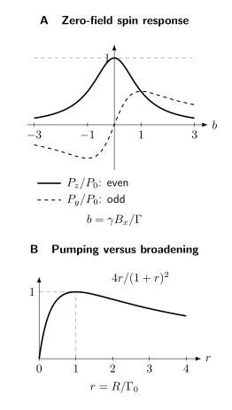
The minimal Bloch model explains two practical limits. A: with and , the even longitudinal response is and the odd transverse response is . Only the central part of the latter is linear. B: increasing pump rate eventually broadens the response faster than it improves polarization. The normalized small-field slope , where , peaks at . These curves neglect spatial transport, higher spin moments, and probe noise.
Magnetometer Architectures
Section titled “Magnetometer Architectures”Zero-field dispersive magnetometer
Section titled “Zero-field dispersive magnetometer”The steady-state response above is the prototype of a near-zero-field vector channel. The instrument is operated near using magnetic shields, compensation coils, or feedback. A transverse component tips the pumped polarization and produces optical rotation.
Advantages include a direct odd response around zero and no need to track a high carrier frequency. Limitations include a narrow linear range, cross-axis coupling, sensitivity to coil offsets, and ambiguity if several components are large simultaneously. Three-axis operation generally uses orthogonal modulation fields, multiple optical geometries, or feedback that nulls each component.
Driven finite-field resonance
Section titled “Driven finite-field resonance”In an Mx-type magnetometer, circular light prepares polarization and an RF field drives transverse spin resonance. In a Bell–Bloom magnetometer, modulated pump light drives spin precession when the modulation frequency matches the Larmor frequency.
A linear complex response near resonance can be written
Its phase is
up to the instrument’s sign and phase origin. A servo can adjust the drive frequency until the quadrature error vanishes, yielding
The resonant architecture can operate at much larger fields than a zero-field sensor. It inherits RF coil calibration, Bloch–Siegert shifts, drive-phase delays, and line-center systematics.
Free-precession magnetometer
Section titled “Free-precession magnetometer”A pulsed instrument optically pumps the ensemble, turns the pump off, and records a free-induction signal:
The dark interval suppresses pump light shifts and permits frequency estimation from phase accumulation. The estimator must handle finite record length, colored noise, multicomponent Zeeman beats, phase transients, and cycle-to-cycle dead time. A high signal-to-noise sinusoid does not justify a single-frequency model when nonlinear Zeeman components are resolved.
RF atomic magnetometer
Section titled “RF atomic magnetometer”An RF magnetometer applies a bias field so an atomic Zeeman transition is resonant with the AC field of interest. The signal estimates an amplitude and phase in a narrow band:
Tuning the bias field changes the center frequency. Narrow bandwidth rejects broadband noise but also distorts pulses or modulated signals outside the calibrated response. RF magnetometers are useful for low-field NMR and nuclear quadrupole resonance, but are not broadband DC vector sensors.
Scalar versus vector operation
Section titled “Scalar versus vector operation”Scalar operation derives from a precession frequency and can be relatively insensitive to gain drift. Vector operation derives components from amplitudes, phases, or feedback currents and requires calibrated axes.
Scalar does not mean orientation independent. Optical pumping and nonlinear Zeeman structure create heading error. Vector does not mean all three components are independently observable. The response matrix must have full rank:
The condition number of determines how calibration and noise are amplified during inversion.
Differential and array operation
Section titled “Differential and array operation”For two sensors,
Let their gains be
and their fields
Then
Gain mismatch leaks the common field into the gradient channel. Frequency-dependent mismatch, different sensitive volumes, axis misalignment, and modulation-coil cross-talk also limit common-mode rejection.
For baseline vector and a slowly varying component,
The effective baseline joins the response-weighted sensor locations, not necessarily the package centers.
Spin-Exchange Relaxation-Free Operation
Section titled “Spin-Exchange Relaxation-Free Operation”Why spin exchange normally broadens
Section titled “Why spin exchange normally broadens”Alkali atoms collide and exchange electron-spin character at rate
where is alkali density. Spin exchange largely conserves total angular momentum, but transfers atoms among hyperfine manifolds with different precession frequencies. At ordinary field and low polarization, this random switching dephases a coherent ensemble and broadens magnetic resonance.
Heating a cell increases atom number and optical depth, which could improve statistical sensitivity, but it also raises . This collision limit historically prevented arbitrary improvement by density.
Motional narrowing at low field
Section titled “Motional narrowing at low field”In the spin-exchange relaxation-free, or SERF, regime,
Each atom changes hyperfine character many times during one precession period. The ensemble evolves with an averaged precession rather than dephasing after every collision. At low polarization, a schematic spin-exchange relaxation rate is
where depends on nuclear spin, polarization, and the measured mode. This scaling, not a universal coefficient, is the important result. The spin-exchange contribution vanishes quadratically toward zero field.
Hyperfine correlations also slow the electron-spin response. Detailed SERF models introduce a nuclear slowing-down factor and a polarization-dependent effective gyromagnetic ratio. Using the bare electron gyromagnetic ratio in a SERF calibration is incorrect.
What SERF does not remove
Section titled “What SERF does not remove”SERF suppresses one relaxation mechanism. It does not eliminate:
- spin-destruction collisions;
- wall and diffusion relaxation;
- pump and probe power broadening;
- magnetic gradients;
- light shifts;
- radiation trapping;
- photon shot noise and spin-projection noise;
- Johnson magnetic noise from conducting shields and heaters; or
- drift and cross-talk in field-nulling coils.
The small-field condition also limits dynamic range. A large ambient field can take the sensor out of the SERF regime or rotate polarization beyond the linear response. High-sensitivity SERF measurements commonly require magnetic shielding or active cancellation. This makes them excellent for some biomagnetic and fundamental measurements but does not make them automatic replacements for geomagnetic scalar instruments.
Density and temperature tradeoffs
Section titled “Density and temperature tradeoffs”Increasing temperature raises alkali density and , helping reach the SERF condition. It can also:
- raise spin-destruction rate;
- increase optical depth and pump nonuniformity;
- increase required heater power and thermal gradients;
- bring conductive materials and their Johnson noise closer to the cell;
- accelerate coating degradation; and
- make close placement near biological or chemical samples harder.
“Higher density is better” is therefore no more reliable than “longer interrogation is better” in a clock.
Sensitivity, Bandwidth, and Range
Section titled “Sensitivity, Bandwidth, and Range”Noise-equivalent magnetic field
Section titled “Noise-equivalent magnetic field”Let the measured output have transfer function from the declared field component to output. The amplitude spectral density of equivalent input magnetic noise is
A quoted value such as is incomplete without frequency, bandwidth, operating point, spatial configuration, and whether environmental field noise has been subtracted. A gradiometric noise floor is not the same quantity as a single-channel absolute noise floor.
First-order response and bandwidth
Section titled “First-order response and bandwidth”A simple spin response is low-pass. For a complex input proportional to ,
The bandwidth is
Increasing relaxation or feedback can increase bandwidth, but often reduces open-loop gain or increases noise. Feedback can extend linear range while moving calibration from the atomic slope to coil gain, electronics, delay, and loop stability.
For a transient field, the relevant question is not only the flat-band noise floor. Phase delay and amplitude roll-off must be deconvolved or included in the signal model.
Spin-projection-noise baseline
Section titled “Spin-projection-noise baseline”For independent polarized spins with coherent interrogation time , an order-of-magnitude continuous sensitivity is
Order-one factors depend on spin, polarization, duty cycle, measured quadrature, and estimator. Spin exchange creates correlations that can modify simple independent-spin spectra. Entanglement or squeezing can improve the projection-noise term, but cannot remove a light-shift drift or coil-calibration error.
Photon shot noise and backaction
Section titled “Photon shot noise and backaction”For optical rotation with slope , the equivalent input one-sided amplitude spectral density is
To compare with the averaging coefficient defined above, assume white noise over the bandwidth of a rectangular average. Its response is , so
The spectral noise level is therefore times the averaging coefficient in this convention. Their units are dimensionally equivalent, so units alone do not identify which number is quoted. For colored noise or a different averaging filter, use the integral with its actual spectrum and response instead of this white-noise conversion.
More probe photons reduce but perturb the atoms more strongly. The optimum balances photon shot noise, spin noise, power broadening, and light shifts under the actual optical-depth model.
Technical noise can enter through:
- laser intensity, frequency, polarization, and pointing;
- photodetector electronics and digitization;
- heater current and modulation;
- coil-current noise;
- mechanical motion through magnetic gradients;
- shield vibration and remanence;
- nearby electronics and mains harmonics; and
- data-acquisition clock jitter.
A noise budget should measure transfer coefficients rather than merely list possible sources.
Dynamic range and linearity
Section titled “Dynamic range and linearity”For the zero-field dispersive model, the characteristic linear scale is
The exact acceptable range depends on the allowed nonlinearity. If the full response is
then the ratio to its linear approximation is
Keeping gain error below requires approximately
Sensitivity, bandwidth, and linear dynamic range are coupled through . Quoting only the best noise floor conceals this design tradeoff.
Stability and drift
Section titled “Stability and drift”Allan deviation or overlapping Allan deviation can characterize a stationary field estimate. The result combines sensor drift and real field variation unless a stable source or differential channel separates them. Pump detuning, cell temperature, coil offset, shield magnetization, and laser polarization can create long-term floors.
A flat long-term scalar frequency record does not prove vector-axis stability. A vector sensor can rotate physically while maintaining its component gain.
Calibration and Systematic Effects
Section titled “Calibration and Systematic Effects”Measurement equation
Section titled “Measurement equation”A component channel can be represented as
where is the impulse response and denotes convolution. The target measurand is accompanied by:
- applied calibration and feedback fields;
- pump and probe light shifts;
- contact or magnetization fields from nearby polarized matter; and
- other physical or instrumental nuisance fields.
The inverse estimator must use the same axis, sign, delay, and bandwidth conventions as the forward model.
Coil calibration
Section titled “Coil calibration”For a calibration coil,
where is the coil factor and the current. The standard uncertainty is
depends on winding geometry, sensor location and orientation, nearby magnetic material, shield response, frequency, and current return path. Calculating an ideal Helmholtz factor is not enough when the coil is inside a high-permeability shield.
Useful calibration routes include:
- dimensional and current calibration of a characterized coil;
- comparison with an independently calibrated magnetometer;
- frequency calibration using a validated gyromagnetic model;
- mechanical rotation in a known field;
- injected AC fields across the measurement bandwidth; and
- reversal of current and sensor orientation.
The routes can share common inputs and should not be assumed independent.
Axis and response-matrix calibration
Section titled “Axis and response-matrix calibration”For a vector instrument,
The matrix contains gains, nonorthogonality, and cross-axis response. Calibrate it by applying several noncoplanar fields whose amplitudes and directions are known. A least-squares fit should include coil-field covariance and residual background.
Sensor axes can vary with pump and probe alignment, modulation phase, and operating point. Package fiducials are not necessarily magnetic axes.
Heading error
Section titled “Heading error”A scalar heading test rotates the sensor relative to a field of constant magnitude. The heading error is
Sources include:
- nonlinear Zeeman splitting and orientation-dependent line weights;
- unresolved contributions from both hyperfine manifolds;
- light shifts whose direction follows the optical axis;
- RF polarization and Bloch–Siegert shifts;
- cell and coil anisotropy;
- dead zones where pumping or detection vanishes; and
- fitting one line to a changing multicomponent spectrum.
Testing only two opposite headings can miss even angular harmonics. Characterization should cover the solid angle relevant to operation and repeat at several fields, temperatures, and pump powers.
Light-shift and power extrapolation
Section titled “Light-shift and power extrapolation”Reverse pump helicity, change detuning, vary optical power, and introduce dark evolution to separate light shifts. A linear extrapolation to zero power is credible only if the measured range is linear and the zero-power intercept refers to the same atomic state and estimator.
Pump and probe changes can alter polarization, line weights, temperature, and signal-to-noise ratio at the same time. A global model with these nuisance changes is stronger than a one-variable correction.
Gradients, motion, and diffusion
Section titled “Gradients, motion, and diffusion”Atoms moving through a nonuniform field accumulate different phases. In a ballistic or diffusive cell, this produces relaxation, line distortion, and a response-weighted location. Motion of the whole sensor through a static gradient produces a time-dependent field:
This is central in wearable biomagnetism and mobile geomagnetic sensing. An accelerometer or optical tracker can aid artifact modelling, but requires calibrated time alignment and a measured field map.
Magnetic shields and Johnson noise
Section titled “Magnetic shields and Johnson noise”High-permeability shields reduce ambient field and gradient but introduce:
- remanent field and hysteresis;
- temperature-dependent permeability;
- magnetic viscosity and slow relaxation;
- vibration-to-field coupling;
- Johnson-current magnetic noise from conductive layers; and
- altered calibration-coil geometry.
Demagnetization procedures and waiting time should be documented. Environmental noise measured outside the sensor is not automatically the noise inside the shield, and vice versa.
Array cross-talk
Section titled “Array cross-talk”Each OPM in an array can produce modulation, compensation, heater, and feedback fields seen by neighboring sensors. Optical beams can also leak between channels. A linear array model is
where contains all channel control currents and is the coil cross-talk matrix. Measure with each channel driven separately and test whether it depends on frequency, orientation, or shield state.
Uncertainty and covariance
Section titled “Uncertainty and covariance”Let the reported field be
where contains calibration parameters and environmental inputs. First-order propagation gives
where
Covariance is common in arrays because channels share lasers, shields, clocks, field coils, and environmental models. Treating every channel and systematic as independent can substantially understate uncertainty in a source reconstruction or gradient.
Measuring the Frequency Response
Section titled “Measuring the Frequency Response”A field calibration at one frequency determines only one point on the response curve. Inject small sinusoidal fields across the desired band, measure gain and phase, and repeat near the largest expected field offset. For example, a sensor with a 100 Hz first-order bandwidth transmits a 100 Hz input with of its low-frequency gain and a 45° phase lag. Using its DC gain would therefore underestimate that signal’s amplitude.
Reversals test different effects. Reversing coil current isolates terms odd in that current; rotating the sensor changes heading-dependent line weights. Reversing pump helicity can reverse both the useful response and a vector light shift, so that reversal alone cannot separate them.
Applications
Section titled “Applications”Biomagnetism
Section titled “Biomagnetism”Magnetocardiography and magnetoencephalography detect fields generated by bioelectric currents. OPMs can operate without a cryogenic dewar and can be placed close to the body. The benefit is application specific: sensor noise, standoff distance, channel count, bandwidth, source geometry, shielding, and motion artifacts all matter.
Wearable MEG illustrates the full measurement problem. Movement changes the sensor’s location and orientation in a residual field and gradient, often producing artifacts much larger than the neural signal. Active field nulling, accurate sensor tracking, array calibration, reference channels, and source-reconstruction covariance are part of the instrument, not optional post-processing.
A magnetic map is not a direct image of neural current. The inverse source problem is nonunique and requires anatomical, geometrical, and statistical assumptions.
Low-field NMR and MRI
Section titled “Low-field NMR and MRI”Atomic magnetometers can detect nuclear free-induction fields where inductive pickup coils become inefficient. Prepolarization, encoding, and detection can occur in separate regions. Near zero field, spectra are often governed by spin–spin couplings rather than high-field chemical shifts.
The atomic sensor can perturb the sample through bias and modulation coils, and polarized noble gases can produce enhanced contact fields in alkali vapor. The sample–sensor distance, thermal isolation, field homogeneity, and transfer geometry belong in the sensitivity claim.
Geophysics and navigation
Section titled “Geophysics and navigation”Earth-field scalar magnetometers are used for surveys, observatories, space measurements, and anomaly detection. Relevant requirements include:
- operation at fields of order tens of microtesla;
- low heading error over vehicle attitude;
- large dynamic range and fast recovery;
- stable frequency estimation under vibration;
- platform magnetic cleanliness;
- calibrated location and timing; and
- separation of temporal geomagnetic variation from spatial anomalies.
A shielded SERF noise record near zero field does not establish these properties. Finite-field scalar and free-precession architectures are often better matched to geomagnetic operation.
RF sensing and communication
Section titled “RF sensing and communication”An RF atomic magnetometer can be tuned to a carrier or resonance and detect amplitude, phase, and modulation. Narrowband gain can make weak signals visible, including those used in low-frequency communication or nuclear quadrupole resonance.
Performance should be reported as a transfer function, noise spectrum, linearity, and intermodulation response. A strong nearby carrier can shift or saturate the atomic resonance even when the desired sideband is weak.
Materials and magnetic imaging
Section titled “Materials and magnetic imaging”Atomic-vapor cells, cold-atom clouds, and solid-state spins can map fields from magnetized rocks, currents, magnetic particles, superconductors, and mesoscopic samples. Spatial resolution is set by sensor–sample distance, sensitive-volume size, field propagation, and inversion, not detector pixel size alone.
NV-center magnetometry can place spins nanometres to micrometres from a sample and operate over broad conditions. Vapor-cell magnetometers can provide excellent field sensitivity over larger volumes. These are different points in a sensitivity–bandwidth–distance–resolution space, not a single ranking.
Fundamental and comagnetometer measurements
Section titled “Fundamental and comagnetometer measurements”Two spin species can occupy nearly the same volume. A weighted difference of their precession frequencies can reject ordinary magnetic-field noise:
Here are signed coefficients chosen consistently so that the common magnetic contribution is ; substituting two positive frequency magnitudes with signed can spoil the cancellation. The cancellation also requires identical spatial weighting and well-known gyromagnetic ratios. Species-dependent gradients, contact fields, wall shifts, light shifts, and backaction remain. Such comagnetometers can test rotations, symmetry-violating interactions, or exotic spin couplings, but the interpretation belongs to a declared physical model.
Choosing a platform
Section titled “Choosing a platform”| Requirement | Often suitable | Principal cautions |
|---|---|---|
| shielded low-frequency field component | SERF OPM | narrow range, residual fields, light shifts |
| Earth’s-field magnitude | scalar driven or free-precession OPM | heading error, nonlinear Zeeman structure |
| narrowband RF field | tuned RF atomic magnetometer | bandwidth, drive shifts, saturation |
| near-body multichannel biomagnetism | compact OPM array | motion, cross-talk, thermal and geometric constraints |
| nanoscale proximity | defect-spin magnetometer | surface noise, readout contrast, calibration |
| common-mode rejection | atomic gradiometer or array | gain and phase mismatch, baseline definition |
| field-independent frequency comparison | comagnetometer | species-dependent weighting and contact shifts |
Common Pitfalls
Section titled “Common Pitfalls”A scalar sensor still has heading error. Its leading energy splitting depends on field magnitude, but optical pumping, nonlinear Zeeman structure, and detection weights depend on orientation.
A noise floor is not the total uncertainty. Light shifts, axis errors, calibration, and spatial averaging can bias a stable measurement. A differential noise floor can also conceal noise shared by both channels.
SERF suppresses one relaxation mechanism. Spin destruction, diffusion, light shifts, and magnetic noise remain. The fast-exchange, small-field conditions must hold for the measured mode.
Motion changes the field sampled by the sensor. A quiet field map can produce a large time-dependent signal when the sensor moves through its gradient or rotates its sensitive axis.
Related Reading
Section titled “Related Reading”- Magnetic resonance develops driven and pulsed spectroscopy, line shapes, and relaxation.
- NV-center sensing treats defect-spin optical readout and nanoscale field measurements.
- Tests of fundamental symmetries explains comagnetometer mismatch and electric-field reversal channels.
References
Section titled “References”- J. C. Allred, R. N. Lyman, T. W. Kornack, and M. V. Romalis, “High-sensitivity atomic magnetometer unaffected by spin-exchange relaxation,” Physical Review Letters 89, 130801 (2002).
- J. F. Barry et al., “Sensitivity optimization for NV-diamond magnetometry,” Reviews of Modern Physics 92, 015004 (2020).
- W. E. Bell and A. L. Bloom, “Optical detection of magnetic resonance in alkali metal vapor,” Physical Review 107, 1559–1565 (1957).
- W. E. Bell and A. L. Bloom, “Optically driven spin precession,” Physical Review Letters 6, 280–281 (1961).
- E. Boto et al., “Moving magnetoencephalography towards real-world applications with a wearable system,” Nature 555, 657–661 (2018).
- D. Budker and M. Romalis, “Optical magnetometry,” Nature Physics 3, 227–234 (2007).
- D. Budker, W. Gawlik, D. F. Kimball, S. M. Rochester, V. V. Yashchuk, and A. Weis, “Resonant nonlinear magneto-optical effects in atoms,” Reviews of Modern Physics 74, 1153–1201 (2002).
- H. B. Dang, A. C. Maloof, and M. V. Romalis, “Ultrahigh sensitivity magnetic field and magnetization measurements with an atomic magnetometer,” Applied Physics Letters 97, 151110 (2010).
- C. L. Degen, F. Reinhard, and P. Cappellaro, “Quantum sensing,” Reviews of Modern Physics 89, 035002 (2017).
- A. Fabricant, I. Novikova, and G. Bison, “How to build a magnetometer with thermal atomic vapor: a tutorial,” New Journal of Physics 25, 025001 (2023).
- W. Happer, “Optical pumping,” Reviews of Modern Physics 44, 169–249 (1972).
- W. Happer and H. Tang, “Spin-exchange shift and narrowing of magnetic resonance lines in optically pumped alkali vapors,” Physical Review Letters 31, 273–276 (1973).
- W. Happer and A. C. Tam, “Effect of rapid spin exchange on the magnetic-resonance spectrum of alkali vapors,” Physical Review A 16, 1877–1891 (1977).
- JCGM, Evaluation of measurement data: Guide to the expression of uncertainty in measurement, JCGM 100:2008, corrected version 2010.
- JCGM, International vocabulary of metrology: Basic and general concepts and associated terms, JCGM 200:2012, third edition.
- I. K. Kominis, T. W. Kornack, J. C. Allred, and M. V. Romalis, “A subfemtotesla multichannel atomic magnetometer,” Nature 422, 596–599 (2003).
- W. Lee, V. G. Lucivero, M. V. Romalis, M. E. Limes, E. L. Foley, and T. W. Kornack, “Heading errors in all-optical alkali-vapor magnetometers in geomagnetic fields,” Physical Review A 103, 063103 (2021).
- I. M. Savukov and M. V. Romalis, “Effects of spin-exchange collisions in a high-density alkali-metal vapor in low magnetic fields,” Physical Review A 71, 023405 (2005).
- I. M. Savukov and M. V. Romalis, “NMR detection with an atomic magnetometer,” Physical Review Letters 94, 123001 (2005).
- I. M. Savukov, S. J. Seltzer, M. V. Romalis, and K. L. Sauer, “Tunable atomic magnetometer for detection of radio-frequency magnetic fields,” Physical Review Letters 95, 063004 (2005).
- S. J. Seltzer and M. V. Romalis, “Unshielded three-axis vector operation of a spin-exchange-relaxation-free atomic magnetometer,” Applied Physics Letters 85, 4804–4806 (2004).
- V. Shah, S. Knappe, P. D. D. Schwindt, and J. Kitching, “Subpicotesla atomic magnetometry with a microfabricated vapour cell,” Nature Photonics 1, 649–652 (2007).
- D. Sheng, S. Li, N. Dural, and M. V. Romalis, “Subfemtotesla scalar atomic magnetometry using multipass cells,” Physical Review Letters 110, 160802 (2013).
- D. A. Steck, Rubidium 87 D Line Data, revision 2.3.4 (8 August 2025).
- T. M. Tierney et al., “Optically pumped magnetometers: From quantum origins to multi-channel magnetoencephalography,” NeuroImage 199, 598–608 (2019).
- S. Xu et al., “Magnetic resonance imaging with an optical atomic magnetometer,” Proceedings of the National Academy of Sciences 103, 12668–12671 (2006).
Exercises
Section titled “Exercises”1. Zeeman scale and frequency uncertainty
Section titled “1. Zeeman scale and frequency uncertainty”Use
for the manifold.
- Find the Larmor frequency at .
- A fit gives with standard uncertainty . Ignoring uncertainty in , find and its standard uncertainty.
- If an unmodelled heading shift changes the fitted frequency by , express the magnetic bias in nT.
Solution
Convert
The frequency is
The fitted field is
The frequency-fit contribution is
The heading bias is
It is more than four times the statistical standard uncertainty, showing why a precise frequency fit is not the whole uncertainty budget.
2. Zero-field Bloch response
Section titled “2. Zero-field Bloch response”Starting from
derive the steady-state and . Find the field half-width and the zero-field slope. For
find .
Solution
For ,
The steady and equations are
and
The first gives
Substitution gives
and
The half-width is
and the zero-field slope is
Numerically, the factors of cancel:
The useful range for less than gain error would be only about in the simple Lorentzian model.
3. Projection-noise baseline
Section titled “3. Projection-noise baseline”An ensemble contains effectively measured atoms with and
Use the stated estimate for the averaging coefficient .
- Estimate in .
- If contrast and duty cycle together worsen this coefficient by a factor , find the adjusted coefficient.
- An observed flat one-sided amplitude spectral density is . Convert it to the same averaging convention and compare with the adjusted baseline. Assume rectangular averages long compared with the sensor correlation time.
Solution
The gyromagnetic magnitude is and . Thus
For the specified one-sided spectrum, . Consequently,
Equivalently, convert the adjusted baseline to a one-sided spectral level and compare . Directly dividing by mixes conventions.
The projection-noise estimate remains an order-of-magnitude baseline; the spectral conversion does not fix its omitted spin, polarization, correlation, and estimator factors. A quantitative quantum-noise claim requires those factors as well as the measured noise spectrum and filter.
4. Coil calibration with covariance
Section titled “4. Coil calibration with covariance”A coil has
and is driven at
The correlation coefficient between fitted and current calibration is .
- Find the applied field.
- Find its standard uncertainty including covariance.
- Compare with the uncertainty obtained by assuming independence.
Solution
The field is
The covariance is
Using units consistent with ,
Therefore
Ignoring covariance gives
The negative covariance reduces the propagated uncertainty. It must be supported by the joint calibration fit rather than chosen to improve the budget.
5. SERF criterion and narrowing
Section titled “5. SERF criterion and narrowing”An alkali vapor has spin-exchange rate
and effective
Use the schematic estimate
with coefficient one.
- Evaluate and at .
- Repeat at .
- Explain the domain of this estimate.
Solution
At ,
Thus
and
At ,
so
The fast-exchange separation is much weaker, and the schematic expression would give
The quadratic estimate is an asymptotic low-field scaling with a species-, polarization-, and mode-dependent coefficient. It should not be used quantitatively when is no longer small; the coupled hyperfine spin-exchange dynamics must then be solved.
6. Gradiometer gain mismatch
Section titled “6. Gradiometer gain mismatch”Two OPM channels have mean gain and relative mismatch
They measure a common background and a true differential signal .
- Find the desired differential output.
- Find the common-field leakage.
- What relative matching is required to keep leakage below equivalent field?
Solution
The desired output is
The gain difference is
The leaked output is
This is equivalent to at the mean gain, far larger than the signal. To keep the equivalent leakage below ,
In practice a geomagnetic gradiometer often estimates and subtracts channel gains continuously or operates scalar frequency channels. Axis and frequency-response mismatch remain.
7. Heading-parity model
Section titled “7. Heading-parity model”A scalar magnetometer has heading error
Measurements at give, in nT,
Find , , , and . Why would measurements only at and be insufficient?
Solution
The four equations are
Adding all four gives
so
The opposite-heading differences give
and
Using the first equation,
Measurements only at and determine and the combination , but cannot separate the constant and even second harmonic. They also provide no information about . Opposite-heading reversal is not a complete heading characterization.
8. Motion through a residual field
Section titled “8. Motion through a residual field”A sensor with linear range moves by along a residual gradient of . It also rotates its sensitive axis by toward a transverse residual field of .
- Estimate the separate translation and rotation signals.
- Can the nominal range accommodate their worst-case sum?
- If the translation correction uses a position estimate uncertain by , compare its resulting uncertainty with the noise of a sensor having a flat one-sided amplitude spectral density of , averaged for one second. Assume the bandwidth is much greater than 1 Hz and the gradient is exact.
Solution
Translation produces
For an initially perpendicular field and axis, rotation produces
Their sum can reach ; translation alone already exceeds the linear range. Calibration cannot recover a signal recorded in saturation, so the residual field and gradient must be reduced or the range increased before taking data.
The position uncertainty contributes
The ideal one-second white-noise average has uncertainty
The position contribution is about 850 times larger. A low intrinsic noise floor helps only after motion, field maps, axis rotation, and their uncertainties are controlled. Actual sensor filtering changes the averaging formula when its bandwidth is comparable with .