

Atom-Interferometric Sensors
An atom-interferometric inertial sensor infers acceleration, rotation, or a spatial derivative of acceleration from the phase of a matter-wave interferometer. In a three-pulse light-pulse instrument, the leading acceleration phase is
but a sensor result is not obtained by dividing one fitted phase by . The measured phase is periodic, the atoms respond to acceleration over a finite time and spatial region, the optical phase reference moves, and acceleration, rotation, gravity gradients, laser wavefronts, and environmental fields can enter the same readout.
The task is to infer the physical quantity from measured populations, while accounting for periodic phase, imperfect geometry, and nuisance shifts. An atom interferometer supplies a reproducible freely falling probe; calibration and environmental modelling determine how its phase becomes an acceleration or rotation measurement. Atom sensors complement mechanical, optical, and electromagnetic sensors; which instrument is best depends on the measurand, bandwidth, dynamic environment, averaging time, and required traceability.
Helpful background. Atom interferometry derives the Raman/Bragg pulse sequence, optical phases, and wave-packet closure. Quantum sensing explains statistical precision and multiparameter estimation. For quantum-enhanced protocols and matched resource comparisons, see gravimetry and inertial sensing.
Acceleration, Rotation, and Gravity Gradients
Section titled “Acceleration, Rotation, and Gravity Gradients”Sensor axis and phase sign
Section titled “Sensor axis and phase sign”Define
and let
be the acceleration of the atomic trajectory relative to the optical phase reference, projected along the sensor axis. For an ideal three-pulse sequence with a linear Raman frequency-difference chirp in radians per second squared, use
Here contains all modelled phase shifts not assigned to the intended inertial quantity. Reversing the optical phase convention changes several signs together. A report must therefore state the definitions of , , the output port, and the correction sign.
For a stationary vertical gravimeter, it is convenient to point downward and write . A null measurement then gives
This formula is only as accurate as the calibrated finite-pulse scale factor, the reference trajectory, and the systematic-phase model.
Rotation and gradient conventions
Section titled “Rotation and gradient conventions”For launch velocity and angular velocity , the leading rotation phase in the convention used here is
Define the acceleration-gradient tensor by
For Newtonian gravity , so is symmetric when the potential is smooth. Poisson’s equation gives
The trace is therefore approximately zero in a source-free region, not inside matter. Some geodetic literature defines a tensor from derivatives of rather than , reversing this sign. Tensor components without a declared convention are ambiguous.
What an inertial sensor measures
Section titled “What an inertial sensor measures”An accelerometer does not generally report an invariant property of the atoms alone. It measures relative motion between freely evolving atomic wave packets and the phase fronts established by lasers, mirrors, or waveguides. A stationary vertical instrument can infer local free-fall acceleration because its retroreflection mirror is supported by the laboratory while the atoms fall. On a moving platform, the same observable contains platform specific force, rotation, attitude, vibration, and gravity through the navigation equations.
Likewise, an absolute gravimeter does not measure one universal value of . Local gravity depends on position, height, time, Earth tides, atmospheric and hydrological mass redistribution, polar motion, and nearby objects. The measurand must include a location, epoch or averaging interval, reference height, tide convention, and environmental correction policy.
From Phase to a Sensor Result
Section titled “From Phase to a Sensor Result”A multiparameter measurement model
Section titled “A multiparameter measurement model”One interrogation can be represented locally as
where labels a configuration, and are calibrated response vectors, is a tensor response, is a nuisance bias, and is statistical noise. A set of measurements has the compact form
The parameter vector may contain three acceleration components, three rotation components, selected gradient components, and calibration parameters. Recovering them requires more than counting channels:
- the columns of must be physically identifiable;
- the matrix must have adequate rank and conditioning;
- nuisance parameters must be constrained by calibration or modulation;
- phase wraps must be assigned consistently; and
- the covariance of channels and auxiliary records must be retained.
Two nominally orthogonal axes can be nearly redundant after projection onto the same launch velocity or gravity vector. A small singular value of amplifies both noise and calibration error even when every individual phase is precise.
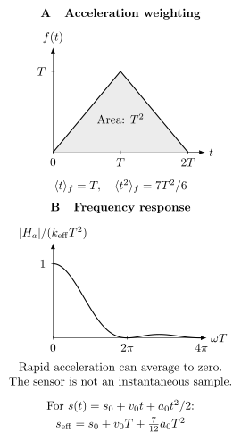
Instantaneous pulses at give a triangular acceleration weight with area . Its mean time is , but its second time moment is . Consequently, a quadratic trajectory is sampled at a response-weighted position different from its position at the middle pulse. For weak linear gravity gradients, use the mean arm trajectory including recoil; finite pulses change the weighting. Panel B plots the magnitude of the Fourier response, which vanishes at nonzero for this ideal sequence.
Calibrated scale factor
Section titled “Calibrated scale factor”For instantaneous pulses and constant acceleration,
Real pulses have finite duration, pulse centers can be asymmetric, the effective wave vector can vary with optical frequency and pointing, and the atoms sample wavefront curvature. A precision result should therefore use
from the actual pulse timing and validated response model. The uncertainty of is a multiplicative uncertainty in the inferred acceleration:
Timing, optical frequency, beam angle, refractive index along the optical path, chirp synthesis, and electronic delay can all enter this calibration. A wavelength traceable to a frequency reference does not by itself calibrate beam alignment or pulse timing.
Periodic readout and dynamic range
Section titled “Periodic readout and dynamic range”A balanced two-port interferometer has an output of the form
so a single ideal population value leaves both a ambiguity and the reflection ambiguity . Finite atom counts add statistical uncertainty. The local slope is also small near a fringe maximum or minimum. Quadrature measurements can remove the reflection ambiguity, but still leave the integer fringe index. The acceleration interval corresponding to one full fringe is
For counterpropagating Raman beams near , . With ,
and
An unmodelled vibration much larger than this can move the result through many fringes. High sensitivity and unambiguous dynamic range are therefore different performance metrics.
Common operating strategies include:
- applying an analysis phase to alternate between both sides of the fringe;
- servoing the chirp or mirror phase so the residual stays near midfringe;
- using an auxiliary accelerometer to predict the integer fringe index;
- fitting a parametric fringe against a deliberately scanned phase;
- using quadrature channels or simultaneous interferometers; and
- using a sequential Bayesian or Kalman estimator that carries the phase posterior between cycles.
Each strategy has a failure mode. A servo can hide cycle slips, an auxiliary sensor can have delay or scale error, and a nonlinear estimator can become biased when its likelihood or wrap prior is wrong. Raw populations, applied phases, residuals, and wrap decisions should be retained.
Midfringe and null operation
Section titled “Midfringe and null operation”Choose so the nominal phase lies at quadrature. For a small residual ,
Null operation steers a controlled parameter, such as , until averages to zero. This is attractive because the result is encoded in a calibrated frequency ramp rather than a large open-loop phase. It does not remove additive systematic phases:
Changing , reversing , or modulating a source mass helps separate terms, but only when the parity and scaling of every relevant nuisance effect are included.
Time-Dependent Acceleration
Section titled “Time-Dependent Acceleration”Triangular response kernel
Section titled “Triangular response kernel”For ideal instantaneous pulses at , , and , the scalar acceleration phase is
with
Thus the instrument reports a time-weighted acceleration, not an instantaneous sample at . With the Fourier convention , the transfer function is
It obeys and has zeros at nonzero . Finite pulses alter the high-frequency response and must be included when vibration correction is pushed near the pulse bandwidth.
For a two-sided acceleration power spectral density satisfying
the phase variance is
One-sided spectra require the corresponding factor-of-two convention. Mixing one-sided and two-sided definitions is a common numerical error.
Cycle sampling and aliasing
Section titled “Cycle sampling and aliasing”If an estimate is produced every cycle time , continuous motion noise is sampled at the cycle rate. Spectral components separated by can alias into the measurement band. Dead time also means that the instrument is blind during part of each cycle, so the sampled transfer function contains preparation and detection windows in addition to the interferometer kernel.
An auxiliary seismometer or mechanical accelerometer should be transformed through the atom sensor’s response:
not merely sampled at the central pulse. Its gain, phase delay, axis projection, mounting point, self-noise, and saturation must be calibrated. A small timing error can become a large residual where vibration spectra are steep.
Interleaved operation can reduce dead time and increase sampling rate by sharing laser pulses among several clouds. It changes the covariance between successive estimates, so the observed averaging law cannot be interpreted as independent white samples without checking that covariance.
Acceleration and Rotation Sensitivity
Section titled “Acceleration and Rotation Sensitivity”Statistical phase baseline
Section titled “Statistical phase baseline”For independent atoms detected in two output ports at midfringe, binomial projection noise gives the approximate phase uncertainty
The corresponding single-cycle acceleration uncertainty is
If cycles are independent and the noise is white, averaging for gives
This is a baseline, not a universal performance law. Atom-number fluctuations, imperfect detection, vibration, oscillator phase, and slow systematics often dominate. Entanglement or spin squeezing can improve the quantum statistical term, but not a wavefront bias or an incorrect reference height.
Acceleration response vector
Section titled “Acceleration response vector”For a nominal one-axis instrument,
The measured projection depends on attitude. A gravimeter tilted by a small angle from the local vertical measures
when horizontal acceleration is negligible. On a moving platform, horizontal specific force leaks into the vertical channel to first order in attitude error. The full calibration is therefore a vector or matrix, not one scalar scale factor.
Axis orthogonality should be measured by rotation, surveying, or a calibrated inertial stimulus. Inferring it only from nominal optical mounts understates alignment uncertainty.
Rotation response vector
Section titled “Rotation response vector”Write
so that
The sensor is blind to rotation components orthogonal to . Three-dimensional rotation sensing therefore requires multiple response vectors spanning three dimensions. With a fixed , every is perpendicular to it. Point-source imaging can therefore recover the two transverse rotation components, together with acceleration along the beam, but remains blind to rotation parallel to that beam. Full three-axis rotation sensing requires another beam orientation or additional geometry (Dickerson et al., 2013).
For , , and transverse speed ,
The maximum projection of Earth’s rotation, , would then produce about . Earth rotation is consequently both a useful calibration signal and a substantial nuisance in gravimetry.
Counterpropagating trajectories
Section titled “Counterpropagating trajectories”Suppose two interferometers use matched and opposite transverse velocities . To leading order,
Then
is acceleration-like, while
is rotation-like. The cancellation fails if the two trajectories have different scale factors, wavefront sampling, launch speeds, pulse timing, contrast, or detection offsets. A gyro uncertainty budget must quantify these mismatches rather than assume parity from the design drawing.
Hybrid inertial sensing
Section titled “Hybrid inertial sensing”Mechanical accelerometers and optical gyroscopes can have high bandwidth and large dynamic range but slowly drifting bias. Atom interferometers can provide a stable low-frequency reference but usually operate cyclically with limited bandwidth. A complementary estimate can be written
where
over the intended band. Kalman filters formulate the same idea with a state model for classical-sensor bias and atom-sensor observations.
Hybridization is not automatic accuracy transfer. The sensors must refer to matched axes, locations, timestamps, sign conventions, and measurands. Lever arms, relative delay, vibration transfer, scale-factor nonlinearity, and classical-sensor saturation can corrupt the fused result. Validation should include injected motion outside the quiet laboratory regime.
Absolute Gravimetry
Section titled “Absolute Gravimetry”Absolute, relative, and conventional
Section titled “Absolute, relative, and conventional”An absolute gravimeter determines acceleration from calibrated time and length or wavelength scales rather than by calibration against another gravimeter. A relative gravimeter measures gravity changes or differences after calibration of its scale factor and drift. Neither label guarantees small uncertainty.
For an atom gravimeter, the primary scale enters through and pulse timing or chirp. Traceability can involve:
- a frequency reference for the Raman optical frequencies and chirp;
- calibrated timing and phase synthesis;
- surveyed optical geometry and vertical alignment;
- characterization of finite-pulse response;
- a measured vertical gravity gradient and reference height; and
- documented environmental and self-attraction corrections.
International gravimeter comparisons remain essential because no artifact-free point on Earth supplies a fixed natural value of . Comparisons test the complete instrument, including effects that are difficult to establish from component calibrations.
Units and resolution
Section titled “Units and resolution”The SI unit is . Gravimetry also uses
Thus is about of terrestrial gravity, while one Eötvös is a gradient unit. A phase resolution of in the numerical example above corresponds to
This conversion is a resolution statement. It is not an uncertainty claim until scale factor, bias, and environmental corrections are evaluated.
Response-weighted gravity
Section titled “Response-weighted gravity”For a weak spatial variation of gravity, a leading-order three-pulse model averages the field along an unperturbed mean arm trajectory:
Here is the mean position of the two recoil-separated arms in the zeroth-order dynamics, measured along the sensor axis. This response description is first order in the spatial inhomogeneity; it is not an exact formula for arbitrary nonlinear potentials. For a locally linear field
define the effective measurement coordinate
For the ideal trajectory
the triangular kernel gives
In an ideal sequence with momentum splitting , the mean initial velocity is the incoming velocity plus half the recoil velocity. Omitting that recoil contribution changes the gradient correction. Finite pulses, launch geometry, and nonlinear gradients require further terms. A quoted physical height should be tied to the instrument reference point by a survey and an explicit trajectory model, not inferred from the chamber drawing alone.
To transfer a result from effective height to a declared reference height , use the locally measured vertical gradient:
where in the chosen upward-height convention. Near Earth’s surface is usually negative, but local mass distributions can change it. The gradient uncertainty and height uncertainty are correlated contributions to the transferred result.
Environmental and geophysical corrections
Section titled “Environmental and geophysical corrections”Local gravity is time dependent. A stationary series commonly contains signals from:
| Effect | Why it enters | Measurements or model |
|---|---|---|
| Solid Earth tides | lunar and solar deformation and potential | stated tide model, coordinates, timestamps |
| Ocean tide loading | elastic response to nearby ocean mass redistribution | loading model and coastal sensitivity |
| Atmospheric attraction and loading | pressure and three-dimensional air-mass changes | local pressure plus declared admittance or model |
| Polar motion | centrifugal acceleration changes as Earth’s rotation pole moves | Earth-orientation data and convention |
| Hydrology | soil moisture, groundwater, snow, and surface water move mass | local sensors or hydrological model when relevant |
| Vertical gradient | instruments and epochs refer to different heights | measured gradient, survey, transfer equation |
| Self-attraction | apparatus, platform, vehicles, and operators produce gravity | mass model, configuration control, modulation tests |
| Nearby construction | elevators, tanks, cranes, and moving masses alter local gravity | site log, exclusion windows, auxiliary monitoring |
One must distinguish a correction convention from a physical prediction. In the zero-tide convention, the permanent direct external tide-generating potential is removed while the Earth’s permanent tidal deformation and its effect on the geopotential are retained. The mean-tide convention retains both; the conventional tide-free description also removes a model of the permanent deformation (IERS Conventions, Chapters 1 and 6). A comparison report should state the tide system rather than merely say “tides corrected.”
Atmospheric correction based on one local pressure coefficient is often a useful operational approximation, but it does not reproduce all three-dimensional atmospheric loading and attraction. Hydrological corrections can be site-specific and model limited. These residuals can remain correlated over long averaging times.
Instrument corrections in a gravimeter
Section titled “Instrument corrections in a gravimeter”A representative corrected result is
where obeys the phase convention declared at the start of the page, are signed instrument and environmental shifts expressed as acceleration, and transfers the response-weighted result to the reference height. An instrument whose electronic error signal has the opposite sign must convert it back to before using this equation. An equally valid convention adds corrections rather than subtracting shifts. The table and equation must use the same sign.
Important instrument terms include:
- Raman or Bragg wave-vector magnitude and optical-frequency chirp;
- timing, finite-pulse, and electronic-delay corrections;
- beam verticality and retroreflection geometry;
- Coriolis phase from transverse atomic velocity and Earth rotation;
- optical wavefront aberration sampled by the transverse atomic distribution;
- gravity-gradient coupling to launch position and velocity;
- two-photon light shifts, magnetic shifts, and residual frequency detuning;
- source-cloud position, temperature, interactions, and detection inhomogeneity;
- mirror vibration and auxiliary-sensor transfer error; and
- self-attraction by the vacuum system, optical table, support, and nearby masses.
Wavefront error illustrates why source properties belong in the measurement model. If an optical phase surface has local curvature , atoms with transverse coordinate sample a phase roughly proportional to
The ensemble bias then depends on transverse temperature, expansion time, cloud position, clipping, detection weighting, and pulse-to-pulse wavefront differences. Mapping the wavefront or varying temperature and trajectory tests the actual phase response more directly than a generic optical flatness specification.
To compare gravimeters, transfer both measurements to a stated reference height and epoch using compatible tide and environmental conventions. Keep the uncertainties in the vertical gradient, survey, and instrument corrections, including shared inputs. Two internally stable instruments can otherwise disagree simply because they report different physical quantities.
Gravity Gradiometry
Section titled “Gravity Gradiometry”Differential measurement and baseline
Section titled “Differential measurement and baseline”Two simultaneous atom interferometers at response-weighted positions and can share the same optical phase reference. For matched acceleration scale factor ,
Let
For a slowly varying gradient,
If the baseline and sensor axis are both along ,
The effective baseline is a difference of response-weighted trajectories, not necessarily the distance between trap centers or vacuum-chamber windows.
For , , and the preceding ,
Common-mode rejection and scale mismatch
Section titled “Common-mode rejection and scale mismatch”Shared mirror vibration is rejected only to the extent that the two interferometers have identical response functions. Let
Then
The second term leaks the large common acceleration into the small differential channel. The same algebra applies to mirror vibration, chirp, and other common inputs. Matching pulse areas but not pulse timing or Rabi frequency can still leave frequency-dependent leakage.
Common-mode rejection should therefore be reported as a transfer function, not one number. Useful tests include injecting mirror motion over frequency, deliberately changing one scale factor, exchanging the two atomic sources, and examining differential residuals against the common channel.
Gradient tensors and closure
Section titled “Gradient tensors and closure”A single vertical baseline measures one projection of . Reconstructing the full tensor requires several independent axis–baseline combinations and careful treatment of rotations between the instrument and local geodetic frame. In a source-free region, Newtonian theory predicts approximately
Symmetry and trace closure are valuable diagnostics, but they are not substitutes for calibration. Misalignment, baseline curvature, rotation coupling, and nearby mass inside the measurement region can produce apparent closure failure.
Over a long baseline, the linear approximation can fail:
The gradiometer then responds to gradient curvature and to the detailed spatial weighting of both interferometers.
Source masses and Newton’s constant
Section titled “Source masses and Newton’s constant”A modulated source mass can produce a differential phase while common Earth gravity and vibration largely cancel. A schematic model is
where includes source-mass density, shape, position, atomic trajectories, and baseline. Solving for requires a gravitational field calculation integrated over the real source and atomic distributions.
The quantum phase can be measured more precisely than the source geometry is known. Density inhomogeneity, positioning, thermal expansion, support structures, trajectory uncertainty, and nearby masses then dominate. Moving the source among several configurations, surveying independently, and fitting one global geometry model provide stronger validation than a single near–far difference.
Gyroscopy and Navigation
Section titled “Gyroscopy and Navigation”Sagnac scale factor
Section titled “Sagnac scale factor”Atom gyroscopes measure a rotation-induced phase associated with the space–time area enclosed by the matter-wave paths. For the simple three-pulse geometry, the response vector
shows three routes to larger signal: larger momentum separation, larger transverse speed, and longer interrogation time. Each also tightens requirements on wave-packet closure, beam size, trajectory knowledge, and dynamic control.
The reported angular velocity is
where denotes the component along . Calibration requires launch velocity, , pulse timing, axis orientation, and any finite-pulse correction. A launch-speed drift is a gyro scale-factor drift.
Rotation–acceleration separation
Section titled “Rotation–acceleration separation”Counterpropagating atomic beams, reversed launch velocities, reversal, and multiple spatial outputs provide different parity channels. Their usefulness depends on a complete parity table:
| Contribution | Velocity reversal | Effective-wave-vector reversal |
|---|---|---|
| uniform acceleration | even | odd |
| leading Sagnac rotation | odd | odd |
| many light shifts | often even | depends on implementation |
| Coriolis from residual transverse velocity | odd in that velocity | odd |
| wavefront phase | trajectory dependent | often odd, not guaranteed |
| detection offset | usually even | usually even |
The labels “odd” and “even” are model statements, not experimental facts. Pulse asymmetry or trajectory changes under reversal can mix channels. A global fit to all configurations, with measured scale-factor mismatch, is usually safer than subtracting nominally opposite phases and discarding the sum.
Dynamic operation
Section titled “Dynamic operation”Laboratory sensors often assume that the Raman resonance, beam overlap, and phase lie in a narrow operating range. A vehicle introduces:
- large and broadband vibration;
- angular motion during the interrogation;
- time-varying Doppler detuning and beam misalignment;
- Coriolis and centrifugal terms;
- lever-arm acceleration between atom and classical sensors;
- changing gravity and attitude;
- interrupted operation and thermal transients; and
- phase excursions through many fringes.
Long interrogation time increases low-frequency scale factor but narrows the tolerable dynamic envelope. High-rate, interleaved, multi-axis, or guided geometries address parts of this tradeoff. Hybrid classical sensors can preserve phase lock and provide high-rate output, while atom data estimate slow bias.
Navigation performance must be evaluated after integrating sensor errors through the navigation equations. A small acceleration bias produces a velocity error growing approximately linearly with time and a position error growing approximately quadratically before aiding and Earth-frame dynamics are included. Bench-top phase sensitivity alone does not establish navigation accuracy.
Noise and Systematic Effects
Section titled “Noise and Systematic Effects”Noise and Bias Mechanisms
Section titled “Noise and Bias Mechanisms”The following categories should be evaluated against the intended measurand:
| Source | Coupling to result | Diagnostic or control |
|---|---|---|
| Atom projection and detection noise | population uncertainty becomes phase noise | atom-number and contrast scaling, two-port normalization |
| Laser phase and oscillator noise | pulse phase is sampled directly | independent phase record, common-source test |
| Mirror vibration | indistinguishable from relative acceleration | isolation, auxiliary sensor, injected-motion transfer test |
| Timing and chirp synthesis | multiplicative scale and additive phase | calibrated clock, phase-continuity and delay tests |
| Beam alignment and tilt | projects gravity and platform acceleration | tilt scans, optical survey, attitude sensor |
| Wavefront aberration | trajectory-dependent optical phase | wavefront map, cloud-position and temperature scans |
| Coriolis effect | transverse velocity couples to rotation | velocity reversal, launch imaging, orientation scan |
| Gravity gradients | launch position and velocity become phase | gradient measurement, trajectory scan, compensation |
| Magnetic fields | Zeeman phase and state-dependent forces | shielding, mapping, field reversal, insensitive states |
| Optical intensity and detuning | ac Stark shifts and pulse-area changes | intensity extrapolation, detuning reversal, pulse diagnostics |
| Atom interactions | density-dependent phase or trajectory | density extrapolation, source-state comparison |
| Detection inhomogeneity | spatial phase is reweighted | imaging, aperture scan, detector model |
| Self-attraction | apparatus masses alter local gravity | mass model, component movement, independent survey |
| Dead time and aliasing | high-frequency noise folds into estimates | cycle-timing model, interleaving, spectral injection |
A physical effect is not intrinsically “statistical” or “systematic.” Rapid zero-mean vibration can contribute statistical variance; an unmeasured mean tilt is a bias; slowly varying hydrology can be either a signal or a correction depending on the measurand.
Wavefront–trajectory coupling
Section titled “Wavefront–trajectory coupling”Let the pulse-dependent transverse optical phase be . The interferometer contribution is
The measured ensemble phase is a nonlinear average over atomic positions, velocities, transition probabilities, and detection weights. It is generally not equal to this expression evaluated at the mean trajectory. Temperature extrapolation can reveal a coupling, but extrapolation to zero temperature is model dependent if clipping or aberrations are nonquadratic. Direct wavefront mapping and controlled trajectory scans provide complementary tests of the phase model.
Coriolis and launch velocity
Section titled “Coriolis and launch velocity”For a vertical gravimeter, Earth rotation produces
The relevant is the response-weighted transverse velocity of the detected ensemble. Selection pulses and apertures can make it differ from the mean velocity measured immediately after launch. Reversing launch velocity, rotating the instrument azimuth, and imaging the detected atoms help constrain the model.
Gravity-gradient coupling and closure
Section titled “Gravity-gradient coupling and closure”In a vertical gradient, the phase depends on initial position and velocity as well as nominal . Schematically,
The same gradient can prevent perfect phase-space closure and reduce contrast. Changing the effective wave vector of the middle pulse can compensate leading gradient effects in suitable geometries, but the frequency step, actual gradient, and residual higher-order terms become new calibration quantities.
Reversal channels
Section titled “Reversal channels”For effective-wave-vector reversal, define
The desired acceleration phase is usually odd. That does not imply that every odd term is acceleration. Coriolis, wavefront, two-photon detuning, and trajectory changes can also have odd components. Nor does every light shift cancel into the even channel when the two reversal configurations use different optical frequencies or pulse efficiencies.
Robust studies use several independent modulations:
- reversal;
- launch-velocity or trajectory reversal;
- interrogation-time scaling;
- instrument azimuth and tilt scans;
- atom number, temperature, and cloud-position scans;
- optical intensity and detuning scans;
- source-mass position modulation; and
- deliberate vibration or rotation injection.
The residuals of a joint model across all configurations are often more informative than any one corrected number.
Uncertainty with covariance
Section titled “Uncertainty with covariance”Let a corrected result be
where contains corrections and calibration or environmental inputs. First-order propagation gives
with Jacobian
and input covariance matrix . Covariance matters when the same tilt sensor, trajectory fit, wavefront map, gravity-gradient measurement, frequency reference, or environmental model affects several corrections.
For a simple quotient ,
Adding correction uncertainties in quadrature is justified only after independence has been established or covariance shown negligible.
Stability and nonstationarity
Section titled “Stability and nonstationarity”Allan-family statistics are useful for sampled inertial data, but their interpretation depends on gaps, drift removal, cycle covariance, and environmental signals. A region suggests white sample noise; it does not prove that systematic effects are absent. A long-term floor can arise from environmental correlation, wrap errors, calibration drift, or an estimator that is not stationary.
Report the sampling interval, dead time, preprocessing, removed offsets or drifts, and confidence intervals. When the signal itself varies, such as tidal gravity, analyze residuals after a declared physical model and retain the model uncertainty.
Common Pitfalls
Section titled “Common Pitfalls”A population is not a unique phase. A single cosine readout has a reflection ambiguity as well as an integer-fringe ambiguity. Neither a smooth fitted curve nor a quiet feedback error proves that the correct branch was followed.
A common optical reference does not guarantee exact rejection. Mismatched acceleration response functions leak common vibration into a gradiometer’s differential phase. Check their frequency dependence, not only a low-frequency scale-factor ratio.
The middle pulse is not automatically the effective measurement height. Gravity is weighted over the trajectory. A spatial gradient couples to launch velocity, recoil, and the second moment of the response kernel.
Wave-vector reversal also reverses some unwanted phases. Coriolis and wavefront effects can enter the same odd channel as gravity. Velocity, temperature, and trajectory scans provide additional information needed to separate them.
Further Connections
Section titled “Further Connections”- Atom interferometry derives pulse sequences and phase accumulation.
- Gravimetry and inertial sensing examines independent-atom baselines, squeezing, and information per unit time.
- Laser cooling explains source temperatures and velocity distributions that determine wavefront sampling.
- Frequency standards connects optical frequency and timing references to calibrated outputs.
- Fundamental constants relates recoil measurements of to the fine-structure constant.
References
Section titled “References”- P. Asenbaum et al., “Phase shift in an atom interferometer due to spacetime curvature across its wave function,” Physical Review Letters 118, 183602 (2017).
- K. Bongs et al., “Taking atom interferometric quantum sensors from the laboratory to real-world applications,” Nature Reviews Physics 1, 731–739 (2019).
- B. Canuel et al., “Six-axis inertial sensor using cold-atom interferometry,” Physical Review Letters 97, 010402 (2006).
- P. Cheinet et al., “Measurement of the sensitivity function in a time-domain atomic interferometer,” IEEE Transactions on Instrumentation and Measurement 57, 1141–1148 (2008).
- P. Cheiney et al., “Navigation-compatible hybrid quantum accelerometer using a Kalman filter,” Physical Review Applied 10, 034030 (2018).
- A. D. Cronin, J. Schmiedmayer, and D. E. Pritchard, “Optics and interferometry with atoms and molecules,” Reviews of Modern Physics 81, 1051–1129 (2009).
- G. D’Amico et al., “Canceling the gravity gradient phase shift in atom interferometry,” Physical Review Letters 119, 253201 (2017).
- S. M. Dickerson, J. M. Hogan, A. Sugarbaker, D. M. S. Johnson, and M. A. Kasevich, “Multiaxis inertial sensing with long-time point source atom interferometry,” Physical Review Letters 111, 083001 (2013), doi:10.1103/PhysRevLett.111.083001; author manuscript.
- A. Gauguet, B. Canuel, T. Lévèque, W. Chaibi, and A. Landragin, “Characterization and limits of a cold-atom Sagnac interferometer,” Physical Review A 80, 063604 (2009).
- T. L. Gustavson, P. Bouyer, and M. A. Kasevich, “Precision rotation measurements with an atom interferometer gyroscope,” Physical Review Letters 78, 2046–2049 (1997).
- JCGM, Evaluation of measurement data: Guide to the expression of uncertainty in measurement, JCGM 100:2008, corrected version 2010.
- JCGM, International vocabulary of metrology: Basic and general concepts and associated terms, JCGM 200:2012, third edition.
- J. Junca, J. Kitching, and W. McGehee, “Wavefront mapping for absolute atom interferometry,” Physical Review Letters 136, 143402 (2026).
- M. Kasevich and S. Chu, “Atomic interferometry using stimulated Raman transitions,” Physical Review Letters 67, 181–184 (1991).
- J. Lautier et al., “Hybridizing matter-wave and classical accelerometers,” Applied Physics Letters 105, 144102 (2014).
- J. Le Gouët et al., “Limits to the sensitivity of a low noise compact atomic gravimeter,” Applied Physics B 92, 133–144 (2008).
- A. Louchet-Chauvet et al., “The influence of transverse motion within an atomic gravimeter,” New Journal of Physics 13, 065025 (2011).
- J. M. McGuirk, G. T. Foster, J. B. Fixler, M. J. Snadden, and M. A. Kasevich, “Sensitive absolute-gravity gradiometry using atom interferometry,” Physical Review A 65, 033608 (2002).
- S. Merlet et al., “Comparison between two mobile absolute gravimeters: optical versus atomic interferometers,” Metrologia 47, L9–L11 (2010).
- T. M. Niebauer, “The effective measurement height of free-fall absolute gravimeters,” Metrologia 26, 115–118 (1989).
- A. Peters, K. Y. Chung, and S. Chu, “Measurement of gravitational acceleration by dropping atoms,” Nature 400, 849–852 (1999).
- G. Petit and B. Luzum, editors, IERS Conventions (2010), IERS Technical Note 36 (2010).
- G. Rosi, F. Sorrentino, L. Cacciapuoti, M. Prevedelli, and G. M. Tino, “Precision measurement of the Newtonian gravitational constant using cold atoms,” Nature 510, 518–521 (2014).
- A. Roura, “Circumventing Heisenberg’s uncertainty principle in atom interferometry tests of the equivalence principle,” Physical Review Letters 118, 160401 (2017).
- D. Savoie et al., “Interleaved atom interferometry for high-sensitivity inertial measurements,” Science Advances 4, eaau7948 (2018).
- F. Sorrentino et al., “Sensitive gravity-gradiometry with atom interferometry: progress towards an improved determination of the gravitational constant,” New Journal of Physics 12, 095009 (2010).
- X. Wu et al., “Gravity surveys using a mobile atom interferometer,” Science Advances 5, eaax0800 (2019).
- H. Wziontek et al., “Status of the International Gravity Reference System and Frame,” Journal of Geodesy 95, 7 (2021).
Exercises
Section titled “Exercises”1. Phase sensitivity and ambiguity
Section titled “1. Phase sensitivity and ambiguity”An atom accelerometer has
contrast , detected atoms per cycle, and cycle time .
- Find the ideal acceleration scale factor.
- Find the acceleration interval corresponding to one full fringe.
- Estimate the projection-noise-limited acceleration per cycle.
- Estimate the white-noise uncertainty after .
Solution
The scale factor is
One full fringe corresponds to
The phase baseline is
Therefore
For independent white cycles,
The last number excludes vibration, detection excess noise, dead-time aliasing, and systematic uncertainty.
2. Chirp null and scale-factor uncertainty
Section titled “2. Chirp null and scale-factor uncertainty”A vertical gravimeter uses
Its null chirp is
and the evaluated additive systematic phase is
- Find the corrected in the convention of this page.
- Find the shift that would result from forgetting the systematic phase.
- If , find the corresponding standard uncertainty contribution.
Solution
Use
The chirp term is
and the phase correction is
Thus
Forgetting the phase would bias the reported result high by
The multiplicative wave-vector contribution is approximately
The calculation assumes that the phase correction and wave-vector calibration are independent.
3. Effective measurement coordinate
Section titled “3. Effective measurement coordinate”For the ideal triangular kernel, let
- Show that .
- Evaluate for , , and .
- If the vertical gradient in the same coordinate is , find the gravity difference between and .
Solution
By definition,
The triangular-kernel moments are
and
Therefore
Numerically,
The gravity difference is
The sign follows the chosen coordinate. A physical upward-height convention may have the opposite gradient sign.
4. Gradiometer scale-factor leakage
Section titled “4. Gradiometer scale-factor leakage”Two interferometers have
Their effective baseline is , the gravity gradient is , and the common mirror acceleration during a noisy interval is .
- Find the desired differential gravity phase.
- Find the leaked common-mode phase.
- Express the leakage as an apparent gravity gradient.
- What relative scale matching is required to keep this apparent gradient below under the same vibration?
Solution
The differential acceleration is
The desired phase is
The scale mismatch is
so the common-mode leakage is
The apparent gradient is
To keep the leakage below ,
This is a low-frequency estimate. Frequency-dependent response mismatch must be checked with the actual vibration spectrum.
5. Rotation from opposite launch velocities
Section titled “5. Rotation from opposite launch velocities”Two matched interferometers use transverse velocities with
Their measured phases are
Assume the response vectors are aligned with the rotation component of interest and systematic phases have been corrected.
- Find the acceleration-like and rotation-like phases.
- Find the inferred angular velocity.
- If the two acceleration scale factors differ by while the common acceleration is , estimate the leaked phase in the half difference.
Solution
The two parity channels are
and
The rotation scale factor is
Hence
For scale factors and , the half-difference leakage is approximately
Here
so
This is much larger than the rotation signal and shows why matched acceleration rejection is central to atom gyroscopy.
6. Wavefront Curvature over Three Pulses
Section titled “6. Wavefront Curvature over Three Pulses”Assume all three pulses have the same quadratic transverse phase . Between pulses, let . Take , , and .
- Calculate and determine which initial-position terms cancel.
- Two source temperatures change by . Find the phase and apparent acceleration changes, assuming the phase spread is small enough that the fitted ensemble phase equals the mean single-atom phase to leading order.
- Which assumptions would need testing for a real correction?
Solution
Expanding the three squared positions gives
The constant and linear-in-time terms cancel. Thus
Dividing by gives
This result uses ballistic motion, the same curvature at each pulse, quadratic wavefronts, and unbiased detection. Pulse-dependent aberrations, clipping, transition probabilities, and temperature-dependent trajectories can invalidate those assumptions. For a broad phase distribution, the measured phase is the argument of a weighted complex average , not simply .
7. Separating Reversal Channels
Section titled “7. Separating Reversal Channels”An experiment measures four phases:
Assume the model
where . Find , , , and . Which terms would survive a simple effective-wave-vector half-difference at fixed ?
Solution
Orthogonality of the four parity patterns gives
and
Using the table,
At fixed , the effective-wave-vector half-difference is
It retains both the desired -odd acceleration-like term and the rotation-like term . Effective-wave-vector reversal alone cannot separate them.
8. Design a field gravimetry campaign
Section titled “8. Design a field gravimetry campaign”A team plans to map a suspected subsurface density anomaly with a mobile atom gravimeter. The expected spatial signal is over . The instrument has white-noise averaging coefficient in the laboratory, a estimated transport offset, and an effective measurement height above its survey marker.
Design a campaign and analysis capable of making a defensible claim about the anomaly. Address station layout, averaging, reference ties, height and gradient, environmental corrections, transport validation, data rejection, covariance, and reporting.
Solution
A defensible plan could use the following structure.
- Measurand. Define zero-tide gravity at each surveyed marker, transferred to one common physical height and reference epoch. State whether the target is absolute gravity, station differences, or a residual after a regional gravity model.
- Station layout. Use stations closer than the expected anomaly scale, for example –, plus stations well outside the suspected body to constrain the background trend. Repeat a base station at the start, middle, and end of each loop.
- Averaging. The white-noise estimate reaches in about , but field vibration and correlated environmental noise invalidate adopting that time blindly. Use longer repeated occupations and verify the observed stability and residual distribution at each station.
- Transport offset. A offset is one third of the target signal. Use closed loops, repeated stations after transport, reversed instrument orientation where supported, and an independent relative gravimeter or second absolute instrument. Model a loop- or transport-dependent offset rather than treating all stations as independent.
- Height transfer. Survey the instrument reference point and marker at every occupation. Measure the local vertical gradient instead of using one nominal free-air value where nearby terrain or structures vary. Propagate gradient and height covariance.
- Environment. Apply declared solid-Earth tide, ocean-loading, atmospheric, and polar-motion models. Monitor pressure, rainfall, groundwater where relevant, nearby vehicles, tanks, elevators, and personnel. Keep a site activity log.
- Instrument diagnostics. Record raw populations, contrast, wraps, auxiliary vibration, tilt, atom-cloud diagnostics, and all configuration changes. Predefine rejection for loss of lock, saturation, excessive tilt, or failed source preparation.
- Analysis. Fit station gravity, temporal environmental terms, base drift or transport offsets, and a smooth regional background jointly. Retain covariance induced by shared tide models, height surveys, gradient estimates, and base ties.
- Validation. Repeat the traverse in reverse order and on another day, include blind station labels during the first analysis, and compare independent processing pipelines or instruments.
- Report. Publish station coordinates, reference heights, epochs, valid data fractions, signed corrections, uncertainty covariance, residuals, repeated-base closure, and the spatial model used to infer the anomaly.
The laboratory sensitivity indicates that statistical resolution may be adequate. The campaign is credible only if transport, height, environmental, and spatial-background uncertainties are shown to be smaller than the signal.