

Interferometry
Interferometry is the art of splitting a wave or quantum amplitude into alternatives, letting those alternatives accumulate relative phase, and recombining them so that phase becomes an observable intensity, count rate, or fringe displacement. It is one of the most important experimental languages of quantum mechanics because it makes phase measurable without treating phase itself as a directly displayed object.
This page explains interferometry as a technique family. The classical wave background is reviewed in Classical Waves and Interference. Matter-wave platforms are surveyed in Interference With Matter. For the probability calculation, use Probability Amplitudes and Born Rule.
The quantum-optical Mach–Zehnder unitary, coherent shot-noise baseline, and squeezed-input phase readout are developed at Interferometers.
Interferometer Logic
Section titled “Interferometer Logic”An interferometer has four conceptual parts:
- a coherent source;
- a splitter that creates alternatives;
- a region where the alternatives acquire different phases;
- a recombiner and detector that convert relative phase into observed probabilities.
Let and be the two branch amplitudes at a chosen output, including the splitter, propagation, and recombiner factors. Then
Writing gives
The last term is the interference term. It is the reason an interferometer can measure a small path change, potential change, acceleration, rotation, refractive-index change, magnetic flux, or gravitational phase shift. The device translates a phase difference into a count-rate difference.
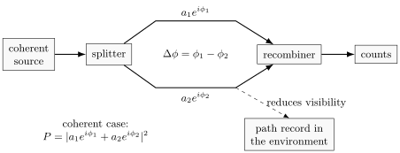
Interferometers share a common logic even when the hardware differs: prepare coherence, split amplitudes, accumulate relative phase, recombine, and read out counts. Environmental records reduce visibility because they make the alternatives distinguishable.
Optical Interferometers
Section titled “Optical Interferometers”Classical optical interferometers were essential before quantum mechanics. They established a mature laboratory grammar for phase, coherence, path difference, and fringe visibility. Later quantum experiments inherited that grammar but changed the interpretation of weak beams and single detection events.
In a simple optical two-beam interferometer, a path-length difference produces phase
for two paths in the same medium, with the wavelength in that medium. For varying refractive index, use the optical path and the vacuum wavelength. Moving one Michelson mirror by changes the round-trip path by . A common fringe model is
where is the visibility and is a fixed offset from the instrument. In a balanced ideal interferometer approaches . In a real instrument it is reduced by unequal intensities, finite bandwidth, source size, vibration, polarization mismatch, detector averaging, and uncontrolled environmental phase noise.
Familiar optical designs include Michelson, Mach–Zehnder, Fabry–Perot, Sagnac, and Ramsey-style separated-field arrangements. Their hardware differs, but each makes a relative phase observable. A Michelson interferometer is naturally sensitive to path length. A Sagnac interferometer is naturally sensitive to rotation. A Fabry–Perot cavity enhances phase sensitivity by multiple passes and resonant buildup.
The two-pulse unitary, finite-pulse fringes, detuning estimators, and clock feedback application are developed in Ramsey Interferometry.
For quantum mechanics, the key lesson is not that light is merely a classical wave. The same optical apparatus can be operated at low intensity, where detections occur one by one. The accumulated counts still follow the interference probabilities. Individual clicks and first-order fringes alone do not distinguish a single-photon source from attenuated classical light. Measurements such as antibunching test additional photon statistics.
Beam Splitters as Amplitude Devices
Section titled “Beam Splitters as Amplitude Devices”A beam splitter should be understood as a device that transforms input amplitudes into output amplitudes. In an ideal two-port model, one may write schematically
where is a unitary matrix when loss is neglected. Different phase conventions are possible. The physics is in the relative phases and in the fact that amplitudes, not probabilities, are recombined.
For a balanced interferometer with one input and two alternatives of equal magnitude, a detector probability often has the form
These two outputs are complementary. When one is bright, the other is dark. In photon-counting language this means count rates are redistributed between detectors, not that energy is created by constructive interference or destroyed by destructive interference.
This point is easy to miss. Interference changes probabilities at output ports because amplitudes from alternatives add with phase. It does not mean each particle splits into two classical half-particles that later collide.
Phase Sensitivity
Section titled “Phase Sensitivity”Interferometers are phase meters. Near a point where the output changes rapidly with phase, a small phase shift produces a measurable count-rate change. If
then
The largest slope occurs near or , so interferometers are often operated near quadrature rather than at a maximum or minimum.
For independent events, the estimated output fraction has standard deviation . At quadrature, , so error propagation gives
Thus lower visibility directly worsens phase precision in this counting model. This is the shot-noise baseline, not a limit on every possible probe. For squeezed inputs and their sensitivity to loss, see quantum optical interferometers.
Matter-Wave Interferometers
Section titled “Matter-Wave Interferometers”Matter-wave interferometers apply the same amplitude logic to electrons, neutrons, atoms, and molecules. The relevant wavelength is not an optical wavelength but the de Broglie wavelength
The alternatives may be created by crystal diffraction, electrostatic biprisms, material gratings, standing light waves, Raman pulses, Bragg pulses, or other coherent devices. During propagation, the phase can often be written semiclassically as an action phase,
so the propagation contribution to the relative phase is
The total measured phase also includes phases introduced at the splitters and mirrors. In light-pulse atom interferometers, laser phases are essential; imperfectly closed paths can add a separation phase. The action difference alone is not a universal prediction for the output.
Different platforms make different phases accessible:
| Platform | Common splitting method | Example phase sensitivity |
|---|---|---|
| electrons | crystal diffraction, biprisms, nanostructures | electromagnetic potentials, material interactions, enclosed magnetic flux |
| neutrons | perfect-crystal Bragg diffraction | gravity, rotation, magnetic fields, nuclear scattering phases |
| atoms | material gratings, standing waves, Raman or Bragg pulses | acceleration, rotation, gravity gradients, internal-state phases |
| molecules | near-field gratings, optical gratings, time-domain gratings | polarizability, decoherence, environmental phase noise |
The matter-wave lesson is especially important historically. Interference is not tied to a classical electromagnetic field. Massive particles can also carry phase, and localized detections can accumulate into an interference pattern. For the broader matter-wave story, see Interference With Matter. The platform-level Raman and Bragg pulse sequence, acceleration and rotation phases, closure, and calibration are developed in Atom Interferometry.
Which-way information and the output probabilities
Section titled “Which-way information and the output probabilities”A path marker can become correlated with the alternatives before recombination. Write the normalized joint state as
with normalized marker states and orthogonal path states. For a balanced recombiner, choose the output amplitudes . If the marker is ignored, the probabilities are
These probabilities sum to one. For equal path populations, the fringe visibility is . Orthogonal records give and . Marker states that differ only by a phase have : they carry no distinguishable path information and merely shift the fringes.
A person need not read the marker. The loss of contrast follows from its physical correlation with the paths. Uncontrolled phase variations can also wash out an averaged fringe, even without a path marker; visibility alone does not identify the mechanism.
Common pitfalls
Section titled “Common pitfalls”Include both splitter factors. A path amplitude before the recombiner is not yet an amplitude at the detector. Omitting the final factor can give probabilities larger than one.
A dark port redistributes the counts. In a lossless two-port instrument, destructive interference at one detector accompanies constructive interference at the other. Check that the output probabilities sum to one.
Reduced visibility has several causes. Unequal intensities, polarization mismatch, phase noise, and distinguishable path records can all reduce contrast. Test the apparatus before attributing a change to one mechanism.
Exercises
Section titled “Exercises”- A Michelson-style interferometer uses light of wavelength . What phase shift is produced by a change in the round-trip optical path difference?
Solution
Use
Thus
- For , , show that the probability is proportional to .
Solution
Let . Then
For an ideal balanced two-splitter interferometer with unit input probability, , so this becomes .
- In the which-way model, what happens to interference if ?
Solution
The detector states are orthogonal, so the alternatives are perfectly distinguishable in principle. The interference term is multiplied by zero and disappears from the reduced probability. For the balanced recombiner used above, both output probabilities are , independently of the scanned phase.
- Why is operating near quadrature useful for phase measurement?
Solution
For
the slope is
Near or , the magnitude of the slope is maximal, so a small phase change produces the largest first-order change in output probability.
References
Section titled “References”- Y. Aharonov and D. Bohm, “Significance of Electromagnetic Potentials in the Quantum Theory,” Physical Review 115, 485-491, 1959, DOI: 10.1103/PhysRev.115.485.
- P. R. Berman, ed., Atom Interferometry, Academic Press, 1997.
- M. Born and E. Wolf, Principles of Optics, 7th expanded ed., Cambridge University Press, 1999.
- R. Colella, A. W. Overhauser, and S. A. Werner, “Observation of Gravitationally Induced Quantum Interference,” Physical Review Letters 34, 1472-1474, 1975, DOI: 10.1103/PhysRevLett.34.1472.
- A. D. Cronin, J. Schmiedmayer, and D. E. Pritchard, “Optics and Interferometry with Atoms and Molecules,” Reviews of Modern Physics 81, 1051-1129, 2009, DOI: 10.1103/RevModPhys.81.1051.
- L. Mandel and E. Wolf, Optical Coherence and Quantum Optics, Cambridge University Press, 1995.
- H. Rauch and S. A. Werner, Neutron Interferometry: Lessons in Experimental Quantum Mechanics, 2nd ed., Oxford University Press, 2015.